
Catalyst degradation detection device

a detection device and catalyst technology, applied in mechanical equipment, machines/engines, electric control, etc., can solve the problems of increasing the risk of fluctuation center and the decline of the oxygen storage function of catalysts

Active Publication Date: 2012-12-20
TOYOTA JIDOSHA KK
View PDF6 Cites 14 Cited by
  • Summary
  • Abstract
  • Description
  • Claims
  • Application Information

AI Technical Summary

Benefits of technology

[0015]To achieve the above objective, a catalyst degradation detection device according to the invention includes a calculating unit for calculating an oxygen storage amount, which is used to determine whether a catalyst is degraded, by forcing at least one of a rich-to-lean change and a lean-to-rich change to occur in an air-fuel ratio of an internal combustion engine. The oxygen storage amount obtained as described above is calculated by using a catalyst downstream sensor in response to a change in an oxygen concentration in exhaust gas on a downstream side of the catalyst. Therefore, the oxygen storage amount thus calculated may deviate from a correct value under the influence from deterioration of responsiveness of a change in a signal output from the sensor. Taking into consideration the above problem, the catalyst degradation detection device further includes a measuring unit to measure responsiveness of a change in the signal output from the catalyst downstream sensor in response to the change in oxygen concentration in the exhaust gas on the downstream side of the catalyst. After the measuring unit measures one of the responsiveness of the catalyst downstream sensor at the time of the lean-to-rich change in the air-fuel ratio of the internal combustion engine and the responsiveness of the catalyst downstream sensor at the time of the rich-to-lean change in the air-fuel ratio, a correcting unit corrects the oxygen storage amount calculated by the calculating unit on the basis of the measured responsiveness alone. The oxygen storage amount thus corrected is prevented from deviating from a correct value under the influence from deterioration of the responsiveness of the change in the signal output from the catalyst downstream sensor. Then, a determining unit determines whether the catalyst has degraded on the basis of the corrected oxygen storage amount. Therefore, the determination result obtained by the determining unit is accurate regardless of the responsiveness of the output signal of the catalyst downstream sensor.
[0018]Taking into consideration the above situation, to be able to promptly complete the determination of whether the catalyst has degraded, the determination of whether the catalyst has degraded should be made as described below. That is, when the measurement of one of the rich-to-lean responsiveness and the lean-to-rich responsiveness of the catalyst downstream sensor has already been completed, whether the catalyst has degraded is determined by comparing the oxygen storage amount corrected on the basis of the already measured responsiveness to a threshold value. If the measurement of one of the rich-to-lean responsiveness and the lean-to-rich responsiveness of the catalyst downstream sensor has already been completed, the oxygen storage amount can be corrected on the basis of the measured responsiveness and the corrected oxygen storage amount can be used to determine whether the catalyst has degraded. Therefore, it is not as time-consuming to complete the determination of whether the catalyst has degraded as to measure both the rich-to-lean responsiveness and the lean-to-rich responsiveness of the catalyst downstream sensor for the determination. Therefore, the determination of whether the catalyst has degraded can be promptly completed.

Problems solved by technology

However, when the fuel injection amount is regulated on the basis of the signal output from the catalyst upstream sensor alone, there is still a risk that a fluctuation center when the air-fuel ratio of the internal combustion engine fluctuates in a rich-lean-rich-lean sequence to converge to the stoichiometric air-fuel ratio as described above deviates from the stoichiometric air-fuel ratio due to, for example, manufacturing variability of the sensor.
The oxygen storage function of a catalyst increasingly declines as the catalyst is degrading with time.

Method used


Image

  • Catalyst degradation detection device
  • Catalyst degradation detection device
  • Catalyst degradation detection device

Examples


Embodiment Construction

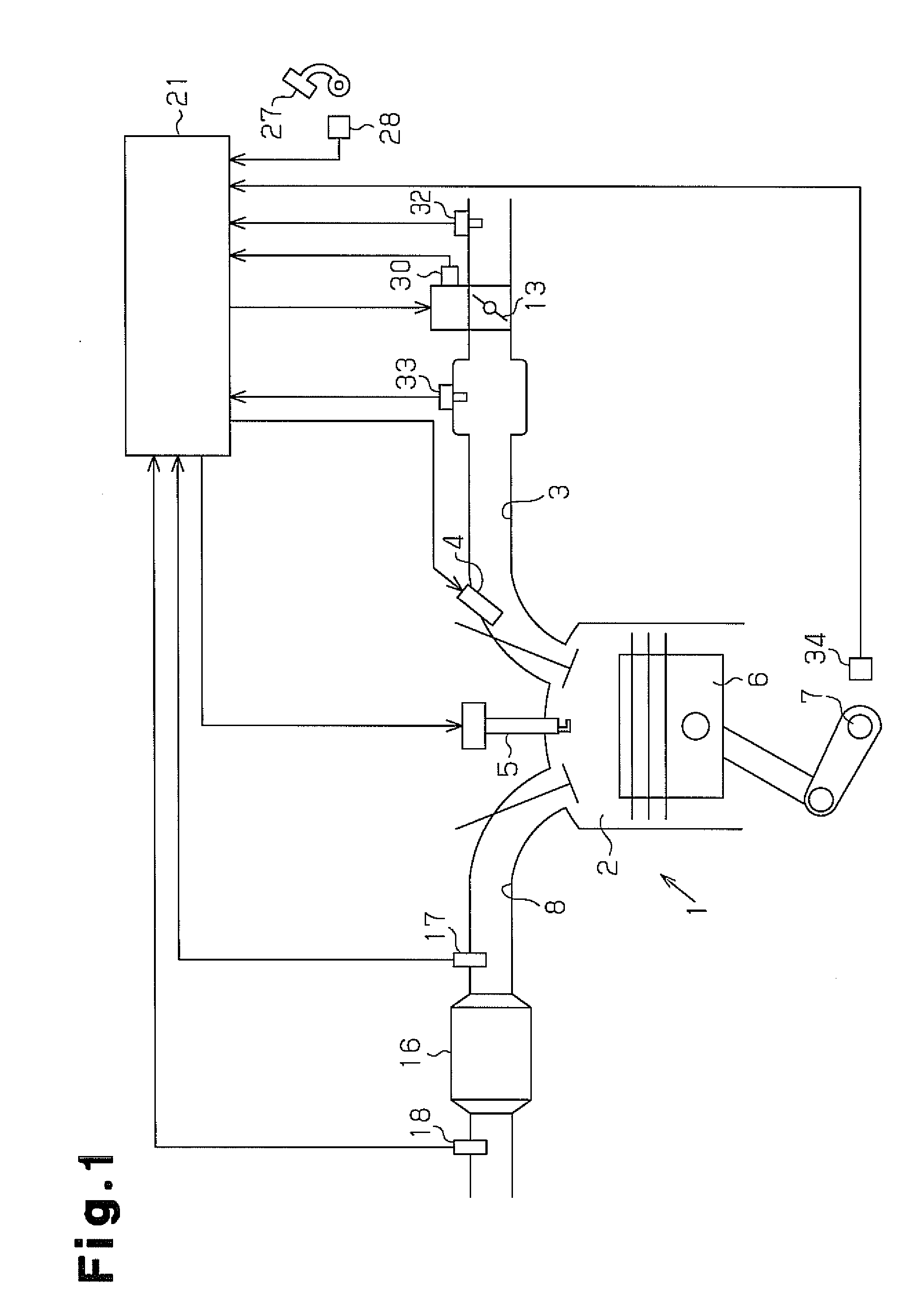
[0029]Hereinafter, an automobile engine according to one embodiment of the invention will be described referring to FIGS. 1 to 7.

[0030]An engine 1 illustrated in FIG. 1 has a throttle valve 13 adapted to open and close in an air intake passage 3 connected to a combustion chamber 2. Air is drawn into the combustion chamber 2 through the air intake passage 3, and fuel injected from a fuel injection valve 4 is supplied to the combustion chamber 2 through the air intake passage 3. Air fuel mixture of gas and fuel supplied to the combustion chamber 2 is ignited by an ignition plug 5 to be combusted. When the air fuel mixture is thus combusted in the combustion chamber 2, a piston 6 reciprocates and a crankshaft 7, which is an output shaft of the engine 1, is rotated.

[0031]The air fuel mixture after being combusted in the combustion chamber 2 is discharged from the combustion chamber 2 as exhaust gas and flows into an exhaust passage 8. The exhaust gas passing through the exhaust passage ...


PUM


Abstract

A catalyst degradation detection device, determines whether a three-way catalyst has degraded on the basis of the maximum value of the amount of oxygen stored by the catalyst. When determining whether the three-way catalyst has degraded, the amount of stored oxygen is calculated, and the responsiveness of change in the output signal of an oxygen sensor to oxygen concentration change in catalyst-downstream exhaust is measured. Then, on the basis of the responsiveness of the oxygen sensor which measured the oxygen storage amount, the oxygen storage amount is corrected by reducing the same such that the worsened the measured responsiveness relative to a reference value, the greater the reduction in the oxygen storage amount used in determining whether the three-way catalyst has degraded. The corrected oxygen storage amount used is prevented from deviating from the correct value on the basis of a worsening of the responsiveness of the oxygen sensor.

Description

TECHNICAL FIELD[0001]The invention relates to a catalyst degradation detection device.BACKGROUND ART[0002]An internal combustion engine mounted in a vehicle, such as an automobile, has an exhaust gas purifying catalyst provided in an exhaust passage so that NOx, HC, and CO of exhaust gas flowing through the exhaust passage are purified by the catalyst. To effectively purify these three components in the exhaust gas, the catalyst is equipped with an oxygen storage function, and stoichiometric air-fuel ratio control is executed to control an air-fuel ratio of air fuel mixture in the combustion chamber of the internal combustion engine to a stoichiometric air fuel ratio.[0003]The oxygen storage function of a catalyst refers to a function that enables oxygen in the exhaust gas to be stored in the catalyst and the oxygen stored in the catalyst to be desorbed from the catalyst and released into the exhaust gas, in accordance with the oxygen concentration in exhaust gas passing through the...

Claims


Application Information

Patent Timeline
IPC IPC(8): F01N3/00F01N11/00
CPCF01N11/007F01N2550/02F01N2560/025F02D41/0295Y02T10/47F02D41/2454F02D2200/0814F02D2200/0816F02D41/1441Y02T10/40
Inventor SATO, MAKOTO
Owner TOYOTA JIDOSHA KK
Learn More