
Bicycle motor control system

Active Publication Date: 2012-12-13
SHIMANO INC
View PDF7 Cites 16 Cited by
  • Summary
  • Abstract
  • Description
  • Claims
  • Application Information

AI Technical Summary

Benefits of technology

[0012]In accordance with a fourth aspect of the present disclosure, the bicycle motor control system of any of the first through third aspects is further configured such that the first mode switching part switches the motor operation mode from the motor driving mode to the motor power generating mode in a circumstance in which communication with respect to the electrical component is disabled and the speed of rotation of the wheel is greater than a predetermined speed of rotation. According to the aspect described above, in a circumstance in which communication with the electrical component is disabled, e.g., in a circumstance in which the supply of electrical power to the motor is stopped and the speed of rotation of the wheel is greater than the predetermined speed of rotation, the motor operation mode is dynamically switched from the motor driving mode to the motor power generating mode. In other words, in a circumstance in which, e.g., operation in the motor power generating mode using electrical power from the motor can be performed in a stable manner, the motor operation mode is dynamically switched from the motor driving mode to the motor power generating mode. The motor operation mode can therefore be switched even more appropriately.
[0014]In accordance with a sixth aspect of the present disclosure, the bicycle motor control system of any of the first through fifth aspects is further provided with a stoppage time calculating part that calculates a time for which communication with the electrical component is stopped. According to the aspect described above, the first mode switching part switches the motor operation mode from the motor driving mode to the motor power generating mode in a circumstance in which communication with the electrical component is disabled for a period that is equal to or greater than a predetermined time. In such a circumstance, the motor operation mode is switched from the motor driving mode to the motor power generating mode in a circumstance in which communication with the electrical component is disabled for the predetermined time or longer. It is thereby possible to restrict the operation mode from switching in a circumstance in which supply of electrical power has stopped temporarily.
[0016]In accordance with an eighth aspect of the present disclosure, the bicycle motor control system of the seventh aspect is further provided with a charge amount monitoring part that monitors an amount of charge in the power source. The second mode switching part switches the motor operation mode from the motor power generating mode to the motor driving mode in a circumstance in which the amount of charge in the power source becomes equal to or greater than a predetermined value. In such a circumstance, since the motor operation mode is switched from the motor power generating mode to the motor driving mode in a circumstance in which the amount of charge in the battery becomes equal to or greater than the predetermined value, rotation of the bicycle wheel can be assisted in a reliable manner after the operation mode has been switched.
[0018]In accordance with a tenth aspect of the present disclosure, the bicycle motor control system of any of the seventh through ninth aspects is further configured such that the second mode switching part switches the motor operation mode from the motor power generating mode to the motor driving mode based on the state of rotation detected by the rotation detecting part in a circumstance in which a number of rotations of the wheel reaches a predetermined number of rotations or in a circumstance in which the distance over which the bicycle travels reaches a predetermined distance. In such a circumstance, since the motor operation mode is switched from the motor power generating mode to the motor driving mode in a circumstance in which the number of rotations of the wheel reaches a predetermined number of rotations or in a circumstance in which the distance over which the bicycle travels reaches a predetermined distance, the motor operation mode can be switched from the motor power generating mode to the motor driving mode in a state in which the supply of electrical power to the motor is stable. Specifically, electrical power can be supplied to the motor in a reliable manner.

Problems solved by technology

In a conventional power-assisted bicycle, in a circumstance in which, e.g., the amount of charge in the battery becomes insufficient, the control system for controlling the motor operation mode becomes unable to issue various types of commands, and the motor operation mode cannot be switched.
Therefore, in a circumstance in which the amount of charge in the battery becomes insufficient, or in similar circumstances, there is a possibility that the motor operation mode will not have been set to the appropriate operation mode.

Method used


Image

  • Bicycle motor control system
  • Bicycle motor control system
  • Bicycle motor control system

Examples


second embodiment

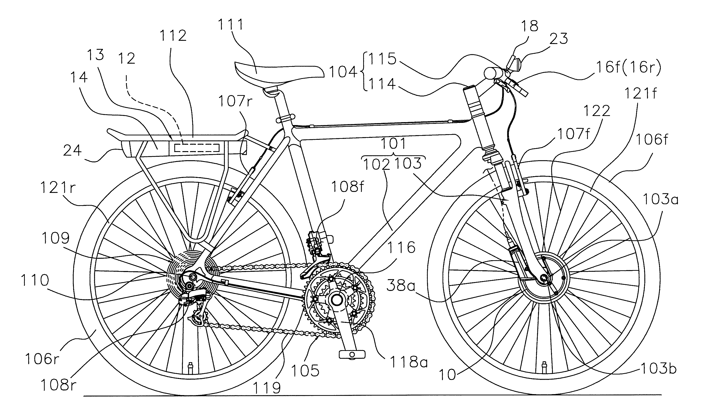
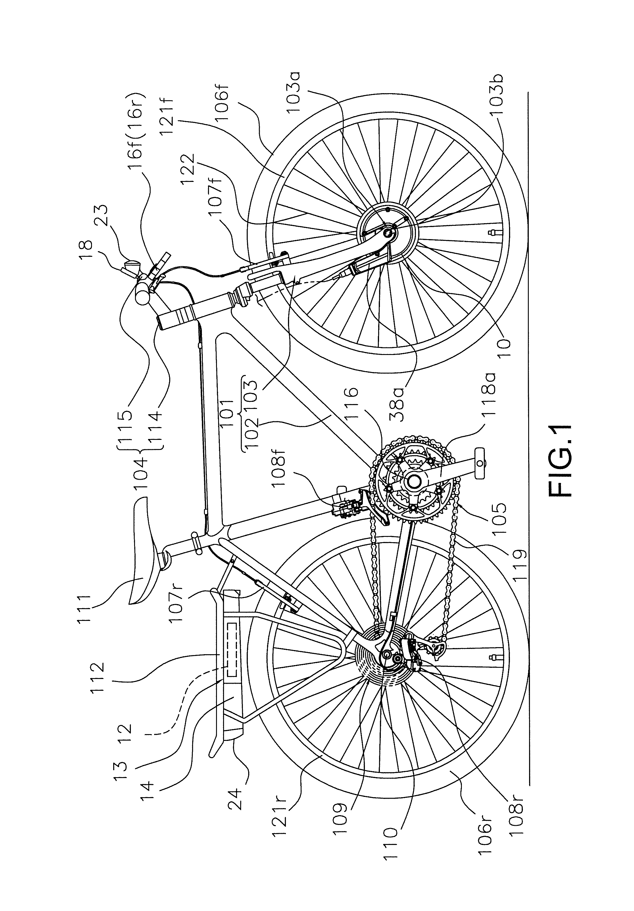
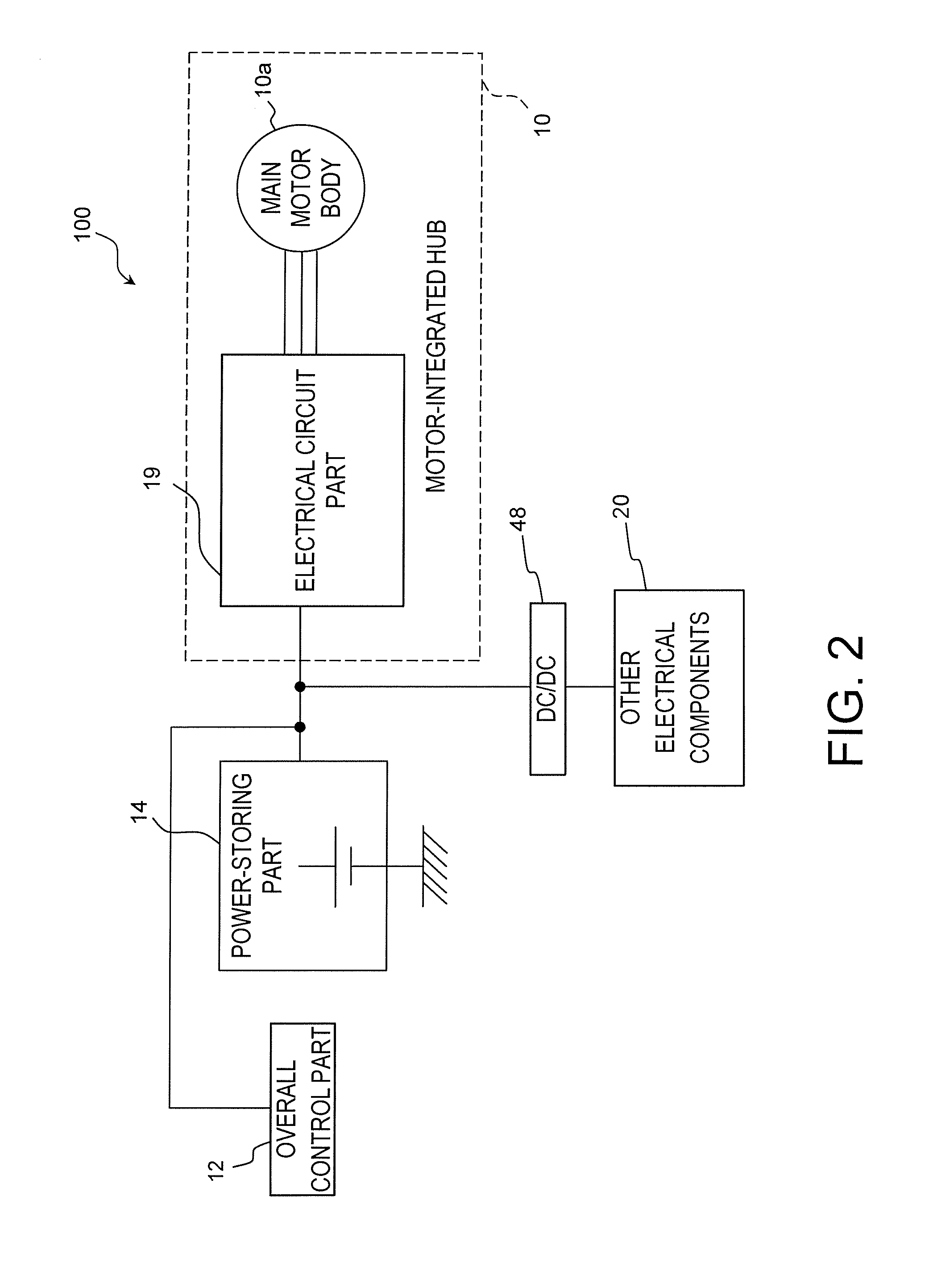
[0072]In the motor control system when the control part 71 for the motor switches the operation mode of the main motor body 10a to the motor power generating mode at step S14, the control part 71 for the motor monitors whether or not the amount of charge in the power-storing part 14 is equal to or greater than the predetermined value (step S15). In a circumstance in which the amount of charge in the power-storing part 14 is equal to or greater than the predetermined value (“Yes” in step S15), the control in step S16 is performed.

[0073]As described above, in the present embodiment, the operation mode of the main motor body 10a is dynamically switched in the motor-integrated hub 10 from the motor power generating mode to the motor driving mode according to the charge state in the power-storing part 14, thereby making it possible to set the operation mode of the main motor body 10a in an appropriate manner. Also, sections of the control that are identical to those in the previous embo...

third embodiment

[0075]In the control process executed by the motor control system as shown in FIG. 6, in a circumstance in which it is determined in step S21 that transmission / reception of signals is not being performed between the motor communication part 72 for the motor and the overall communication part 78, e.g., in a circumstance in which transmission / reception of signals has stopped between the motor communication part 72 for the motor and the overall communication part 78 (i.e., “No” in step S21), the control part 71 for the motor switches the operation mode of the main motor body 10a from the motor driving mode to the motor power generating mode (step S24). As described above, in the present embodiment, the control part 71 for the motor dynamically switches the operation mode of the main motor body 10a from the motor driving mode to the motor power generating mode according to the state of communication between the motor-integrated hub 10 and the electrical component 20, thereby making it ...

fourth embodiment

[0077]In the control process executed by the motor control system as shown in FIG. 7, the control part 71 for the motor determines, in step S32, whether or not the time for which signal transmission / reception between the motor communication part 72 for the motor and the overall communication part 78 has stopped (i.e., stoppage time) is equal to or greater than a predetermined time. In a circumstance in which the signal stoppage time is equal to or greater than the predetermined time (i.e., “Yes” in step S32), the control part 71 for the motor switches the operation mode of the main motor body 10a from the motor driving mode to the motor power generating mode based on a first mode switching signal (step S34).

[0078]As described above, in the present embodiment, the control part 71 for the motor dynamically switches the operation mode of the main motor body 10a from the motor driving mode to the motor power generating mode according to the time for which communication between the moto...


PUM


Abstract

A motor bicycle control system is provided for controlling a motor for assisting rotation of a bicycle wheel. The bicycle motor control system includes a motor communication part and a first mode switching part. The motor communication part performs power line communication with an electrical bicycle component and that changes a motor operation mode of the motor. The first mode switching part is operated either by electrical power supplied via a power line through which the motor communication part performs power line communication, or by electrical power obtained from a generator. The first mode switching part switches the motor operation mode from a motor driving mode in which the motor assist in rotating the bicycle wheel to a motor power generating mode in which the motor outputs electrical power that has been generated using rotation of the bicycle wheel according to a state of communication with the electrical component.

Description

CROSS-REFERENCE TO RELATED APPLICATIONS[0001]This application claims priority under 35 U.S.C.§119 to Japanese Patent Application No. 2010-134552, filed Jun. 11, 2010. The entire disclosure of Japanese Patent Application No. 2010-134552 is hereby incorporated herein by reference.BACKGROUND OF THE INVENTION[0002]1. Field of the Invention[0003]The present invention relates to a bicycle motor control system, and in particular to a bicycle motor control system for controlling a motor for assisting rotation of a bicycle wheel.[0004]2. Background Information[0005]There are known in the art power-assisted bicycles, in which human-powered driving of a bicycle is assisted by an electric motor (for example, see JP-A 2005-304283). In a conventional power-assisted bicycle of such description, when the rider selects the assist mode, the driving force applied by the rider is assisted by an electric motor. In contrast, when the rider selects the regenerative charging mode, electrical power obtained...

Claims


Application Information

Patent Timeline
IPC IPC(8): B62M6/50
CPCB60L7/12Y02T10/642B60L11/007B60L11/1862B60L11/1877B60L2200/12B60L2220/16B60L2220/44B60L2240/421B60L2240/461B60L2240/80B62M6/45Y02T10/7044Y02T10/7005Y02T10/705Y02T90/16B60L7/26B60L1/14B60L7/14B60L15/2009B60L50/20B60L50/52B60L50/66B60L58/13B60L2240/12B60L2240/423B60L2250/16Y02T10/64Y02T10/70Y02T10/72
Inventor SAIDA, TAKAO
Owner SHIMANO INC
Learn More