
Method and apparatus for manufacturing a film with markings

a technology of film and markings, applied in the direction of dough extruders, manufacturing tools, dough shaping machines, etc., can solve the problems of printing difficulties, inks that do not by default have the temperature resistance required, and printing on films using the known methods is always particularly complex

Inactive Publication Date: 2012-12-13
REIFENHAUSER GMBH & CO MASCHFAB
View PDF0 Cites 4 Cited by
  • Summary
  • Abstract
  • Description
  • Claims
  • Application Information

AI Technical Summary

Benefits of technology

[0012]This invention thus makes use of the effect, which is known from the prior art, that cooling the melt web immediately after the exit from the extrusion die by the surface of the cooling roller causes a powerful, occasionally sudden, cooling of the film being produced, which usually gives the film high transparency and high gloss.
[0013]If the melt web and / or the film being produced from it is acted on with a different cooling action in the subregions of the surface corresponding to the markings than the remainder of the surface, then during the extrusion process of the film, it is possible to produce selective differences in transparency or gloss and the like, which appear in the form of markings such as images and inscriptions on the film that is thus produced, without requiring a printing process according to the known methods. The production of markings in the form of inscriptions and / or images can thus be carried out in an in-line fashion during the manufacture of the film and the films produced no longer require any preparation or pretreatment steps for the actual printing process, which can also be eliminated.
[0017]The markings that can be produced with the method proposed according to this invention are thus based on cooling-induced local changes in the properties of the film and can be produced by correspondingly equipped cooling rollers as long as the film has not yet completely cooled. Thus, the markings can be produced not only in the region of or near the first cooling roller against which the melt web rests, but also in the region of or near subsequent cooling rollers over which the film being produced from the melt web is guided, provided that the latter has not yet completely cooled. It is also possible to use a combined exertion of different cooling actions across a plurality of cooling rollers to intensify the effect according to this invention. This, however, requires a synchronization of the cooling rollers according to a repeat pattern.
[0025]In addition to coating the subregions corresponding to the markings with a coating of lower thermal conductivity, such as a lacquer or a plastic or paper layer, it is also possible to mount a sleeve-like cover onto the surface of the cooling roller, which has cutouts that correspond to the subregions of the desired markings so that in this region, the underlying surface of the cooling roller is accessible whereas in the remaining subregions, the sleeve-like cover forms the surface of the cooling roller. Depending on the materials selected for the cover, it is thus possible to produce a higher or lower thermal conductivity in this region relative to the surface of the cooling roller.
[0027]If the surface of the cooling roller in the region of or near the markings to be produced also has a texturing, the film can also undergo a slight embossing in this region, thus making the markings even more visible and more sharply delineated at the edges.

Problems solved by technology

In addition, printing can cause difficulties because, for example, certain products must not contact the applied inks.
Also, inks do not by default have the temperature resistance required, such as in freezer bags, because often the inks used do not adhere sufficiently to the film at low temperatures.
Furthermore, printing on films using the known methods is always particularly complex, a situation which needs improvement.

Method used


Image

  • Method and apparatus for manufacturing a film with markings
  • Method and apparatus for manufacturing a film with markings

Examples

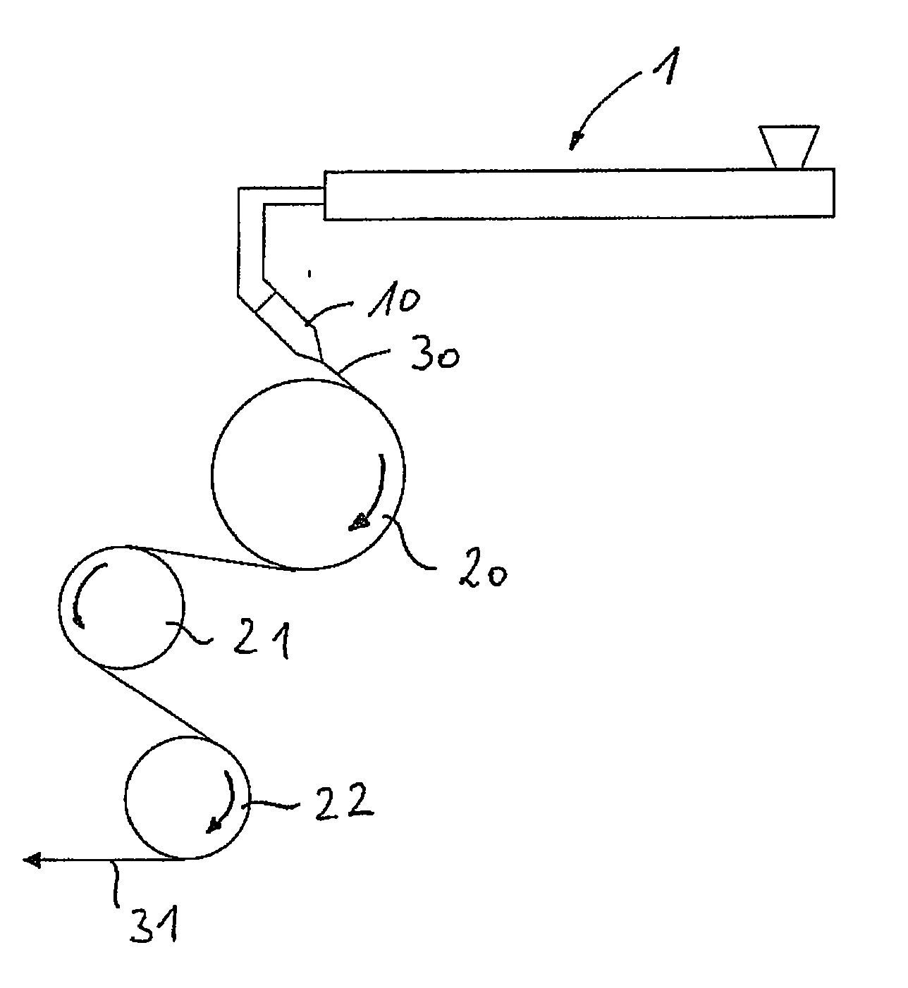
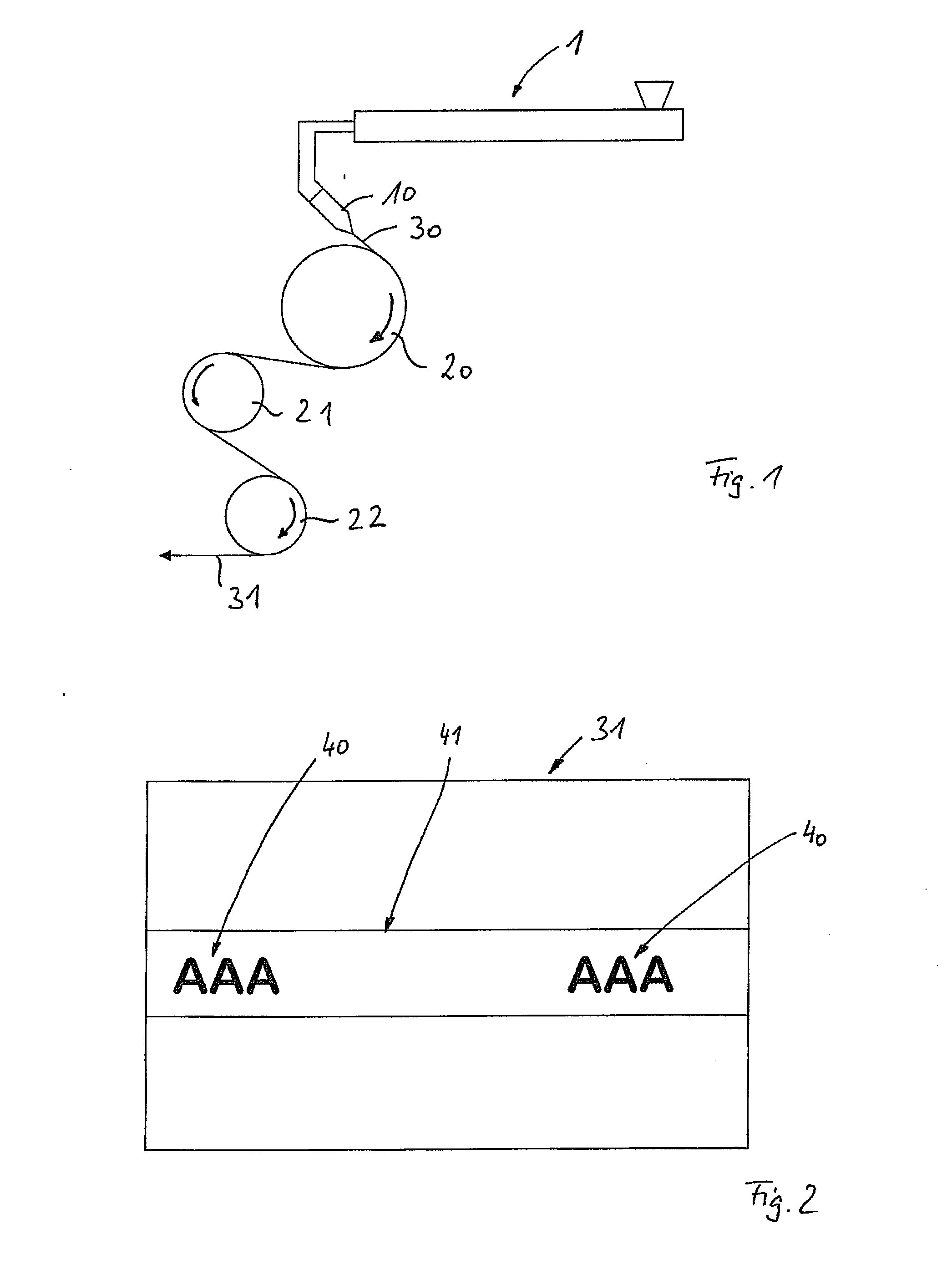

Embodiment Construction

[0031]FIG. 1 shows the method and apparatus for manufacturing a film, which has markings, as shown in FIG. 2.

[0032]In this embodiment of this invention the film 31, for example, has continuous markings in the form of an uninterrupted bar 41, for example with a slightly opaque appearance on the otherwise transparent film and with regularly repeating inscriptions 40 on it.

[0033]In order to manufacture such a film, at least one extruder 1 is used, in which the thermoplastic plastic being used is transformed in an intrinsically known manner into a melt that then emerges in the form of a melt web 30 from an extrusion die 10 situated or positioned downstream of the extruder 1 and is laid against a first cooling roller 20. The cooling roller 20 is temperature-controlled and is driven in a rotary fashion in the rotation direction indicated by the arrows. With the cooled surface of the cooling roller 20 and the existing temperature gradients relative to the melt web 30 that is laid against i...


PUM

PropertyMeasurementUnit
thermal conductivityaaaaaaaaaa
colorsaaaaaaaaaa
coloraaaaaaaaaa

Abstract

A method for manufacturing a film that is provided with markings and is based on a thermoplastic plastic. The thermoplastic plastic is melted in an extruder and emerges from an extrusion die in the form of a melt web. The melt web is conveyed away over a surface of at least one cooling roller and cooled to produce the film. In subregions of the surface of the at least one cooling roller corresponding to the markings, the melt web and / or the film being produced from it is acted on with a different cooling action than in a remainder of the surface.

Description

BACKGROUND OF THE INVENTION[0001]1. Field of the Invention[0002]This invention relates to a method and apparatus for manufacturing a film having markings such as symbols, graphics, letters, and numbers.[0003]2. Discussion of Related Art[0004]It is known to provide a film based on a thermoplastic plastic with markings by printing on the film after it is manufactured. For example, flexographic printing presses are used for this reason, which apply up to seven colors of ink onto the film. This produces markings in the form of images and / or inscriptions.[0005]However, it is often not necessary for such images and inscriptions to be produced in color. A single color, such as “white” is often sufficient. In addition, printing can cause difficulties because, for example, certain products must not contact the applied inks. Also, inks do not by default have the temperature resistance required, such as in freezer bags, because often the inks used do not adhere sufficiently to the film at low ...

Claims


Application Information

Patent Timeline
Patent Type & Authority Applications(United States)
IPC IPC(8): B29C47/88B29C48/08
CPCB29C47/0021B29C47/8845B29C48/08B29C48/914B29C48/9165B29C48/918B29C48/9185
Inventor MEYER, HELMUTHENNES, JOCHEN
Owner REIFENHAUSER GMBH & CO MASCHFAB
Learn More