
Thermal Cutoff Circuit

Inactive Publication Date: 2012-11-22
SERCOMM
View PDF5 Cites 6 Cited by
  • Summary
  • Abstract
  • Description
  • Claims
  • Application Information

AI Technical Summary

Benefits of technology

[0005]The invention is directed to a thermal cutoff circuit applied in an electronic device, wherein the thermal cutoff circuit employs a switch push for enabling a power switch to power up the electronic device in response to a user event. The thermal cutoff circuit further employs a circuit structure capable of preventing the switch push from damage caused by inrush current, which occurs when the electronic device is powered up. Thus, in comparison to conventional thermal cutoff schemes, the thermal cutoff circuit directed by the invention is capable of preventing the switch push from being damaged by inrush current.

Problems solved by technology

When the electronic devices operate above or below the optimum range, damage of system components or malfunction of the electronic device may occur.

Method used


Image

  • Thermal Cutoff Circuit
  • Thermal Cutoff Circuit
  • Thermal Cutoff Circuit

Examples


first embodiment

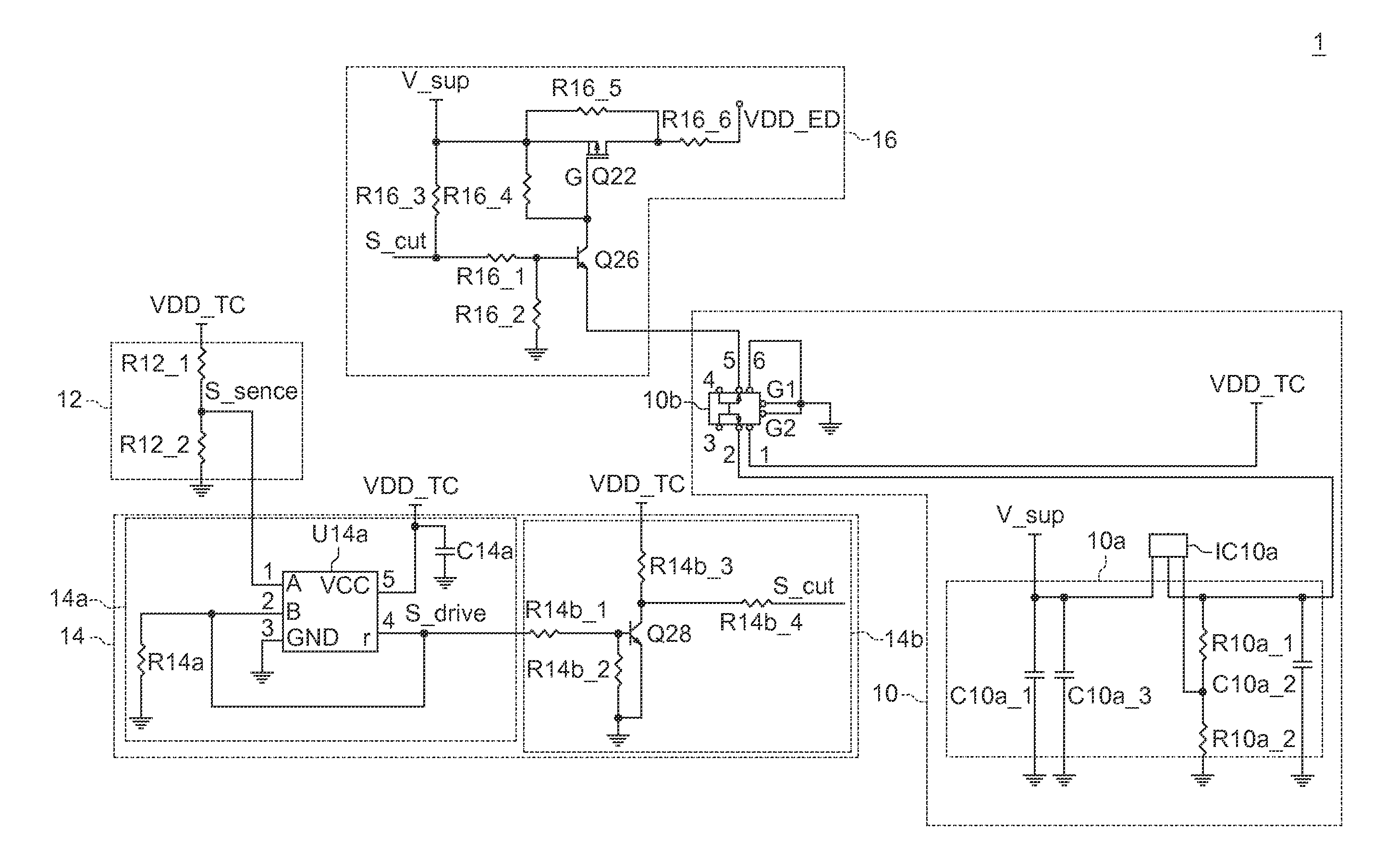
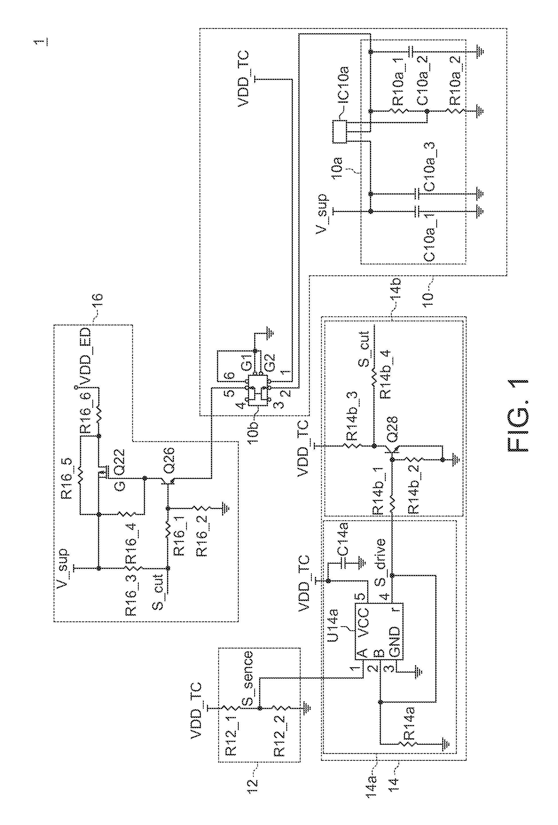
[0011]Referring to FIG. 1, a block diagram of the thermal cutoff circuit according to the first embodiment of the invention is shown. The thermal cutoff circuit 1 is employed in an electronic device (not shown) for applying thermal cutoff protection thereon. The thermal cutoff circuit 1 includes a power unit 10, a thermal sensor 12, a logic unit 14, and a power switch unit 16.

[0012]The power unit 10 powers up the thermal cutoff circuit 1 with a supply voltage VDD_TC in response to a user event. In an embodiment, the power unit 10 includes a power node, a low dropout voltage regulator (LDO) 10a, and a switch push 10b. The power node is connected to other components, e.g. thermal sensor 12 and logic unit 14, of the thermal cutoff circuit 1 and for providing the supply voltage VDD_TC thereto.

[0013]The LDO 10a obtains a supply voltage VDD_TC in response to a power source signal V_sup. In an embodiment, the LDO 10a is implemented with an integrated circuit IC10a, resistors R10a_1, R10a_2...

second embodiment

[0032]Referring to FIG. 3, a block diagram of the thermal cutoff circuit according to the second embodiment of the invention is shown. The thermal cutoff circuit 2 is different from the thermal cutoff circuit 2 of the first embodiment in that a DC to DC converter unit 27 is employed for powering up the electronic device. For example, the DC to DC converter unit 27 includes DC to DC converter 27a and 27b for respectively providing system power signals V1_ES and V2_ES according to the power source signal V_sup.

[0033]The switch push 20b, for example, includes pins #4, #5 and #6, wherein the pin #5 is coupled to the enable pin of the DC to DC converter unit 17, the pin #6 receives the cutoff signal S_cut, and the pin #4 is connect to ground. In response to the user event, the switch push 20b has the pings #5 and #6 shorted together, so as to provide the cutoff signal S_cut as an enable signal of the DC to DC converter unit 17.

[0034]When the cutoff signal S_cut is active, e.g. correspond...


PUM


Abstract

A thermal cutoff circuit for an electronic device including a power unit, a thermal sensor, a logic unit, and a power switch unit is provided. The power unit includes a power switch for powering up the thermal cutoff circuit with a supply voltage in response to a user event. The thermal sensor provides an active thermal sense signal and an inactive thermal sense signal when a temperature of the electronic device exceeds a threshold and does not exceed the threshold, respectively. The logic unit provides an inactive cutoff signal and provides an active cutoff signal respectively according to the inactive thermal sense signal and the active thermal sense signal. The power switch unit powers the electronic device up according to the inactive cutoff signal and stops powering up the electronic device according to the active thermal sense signal.

Description

BACKGROUND OF THE INVENTION[0001]1. Field of the Invention[0002]The invention relates in general to a thermal cutoff circuit, and more particularly to a thermal cutoff circuit employing a switch push.[0003]2. Description of the Related Art[0004]Generally, temperatures of operation for electronic devices typically have an optimum range. When the electronic devices operate above or below the optimum range, damage of system components or malfunction of the electronic device may occur. Thus, it is critical to have devices, which are known as thermal cutoff circuits, for monitoring and managing the temperatures of operation for electronic devices, so as to prevent the electronic devices suffering from physical damage or malfunction.SUMMARY OF THE INVENTION[0005]The invention is directed to a thermal cutoff circuit applied in an electronic device, wherein the thermal cutoff circuit employs a switch push for enabling a power switch to power up the electronic device in response to a user ev...

Claims


Application Information

Patent Timeline
IPC IPC(8): H02H3/02
CPCH02H5/043
Inventor CHIANG, MENG-CHIENCHEN, CHIEN-MING
Owner SERCOMM
Learn More