
Diagnostic method and apparatus for assessing the insulation condition of electrical equipment insulated with oil

a technology for electrical equipment and insulation condition, applied in the direction of testing circuits, air break switches, instruments, etc., can solve the problems of more complicated and expensive gas detection systems based on them, less reliable techniques, and relative unreliable indications

Inactive Publication Date: 2012-11-15
TECHIMP TECHNOLOGIES SA
View PDF3 Cites 13 Cited by
  • Summary
  • Abstract
  • Description
  • Claims
  • Application Information

AI Technical Summary

Benefits of technology

[0029]In particular, the invention has for an aim to provide a diagnostic method and apparatus for assessing the insulation condition of electrical equipment insulated with oil and which can provide reliable and accurate information about the insulation condition of the electrical equipment itself.
[0030]Another aim of the invention is to provide a diagnostic method and apparatus for assessing the insulation condition of a transformer insulated with oil and which can identify in a simple and reliable manner a large number of defects in the insulation of the transformer itself.

Problems solved by technology

In effect, the techniques often conflict (in terms of criteria for interpreting the data collected for the purpose of identifying the source of the gases detected in the oil).
Thus, a first disadvantage of known diagnostic apparatuses and DGA diagnostic methods is that they often lead to relatively unreliable indications.
A second disadvantage of prior art diagnostic apparatuses based on DGA is connected with the need to identify the sources of the gases dissolved in the oil and to distinguish between the different possible sources in a reliable manner.
That means these techniques are less reliable, making the gas detection systems based on them more complicated and expensive.
An erroneous estimate of the concentration of a gas dissolved in the oil nullifies the result of subsequent DGA, which consequently provides an incorrect diagnostic indication or, in the worst of cases, does not detect a possible source of degradation in the insulation of the electrical equipment.
This poses a problem of correctly estimating the gas concentration in the oil as a function of the amount of gas measured in the measuring chamber.
In effect, it takes a relatively long time for the gas to pass from the oil to the measuring chamber (transient of permeation through the membrane) and this leads to errors estimating the concentration.
Thus, another disadvantage of these diagnostic apparatuses is that they are not robust and are subject to gross errors, since there is a real risk of the estimated gas concentration (used in the known diagnostic methods) being wrong (especially during the transients following the formation of the gas in the oil).
By their very nature, therefore, partial discharges are substantially limited in extent to a defect in the insulating system.
In the case of electrical equipment insulated with oil, however, partial discharge analysis (PDA) methods are not used.
In effect, oil insulation is self-restorative, which means that the defects (partial discharge sources) typical of oil insulators are subject to change and even disappear over time.
To this must be added the fact that partial discharges measured on transformers insulated with oil are significantly affected by noise and do not allow use of interpretation methods normally used on equipment with solid insulators.

Method used


Image

  • Diagnostic method and apparatus for assessing the insulation condition of electrical equipment insulated with oil
  • Diagnostic method and apparatus for assessing the insulation condition of electrical equipment insulated with oil
  • Diagnostic method and apparatus for assessing the insulation condition of electrical equipment insulated with oil

Examples


Embodiment Construction

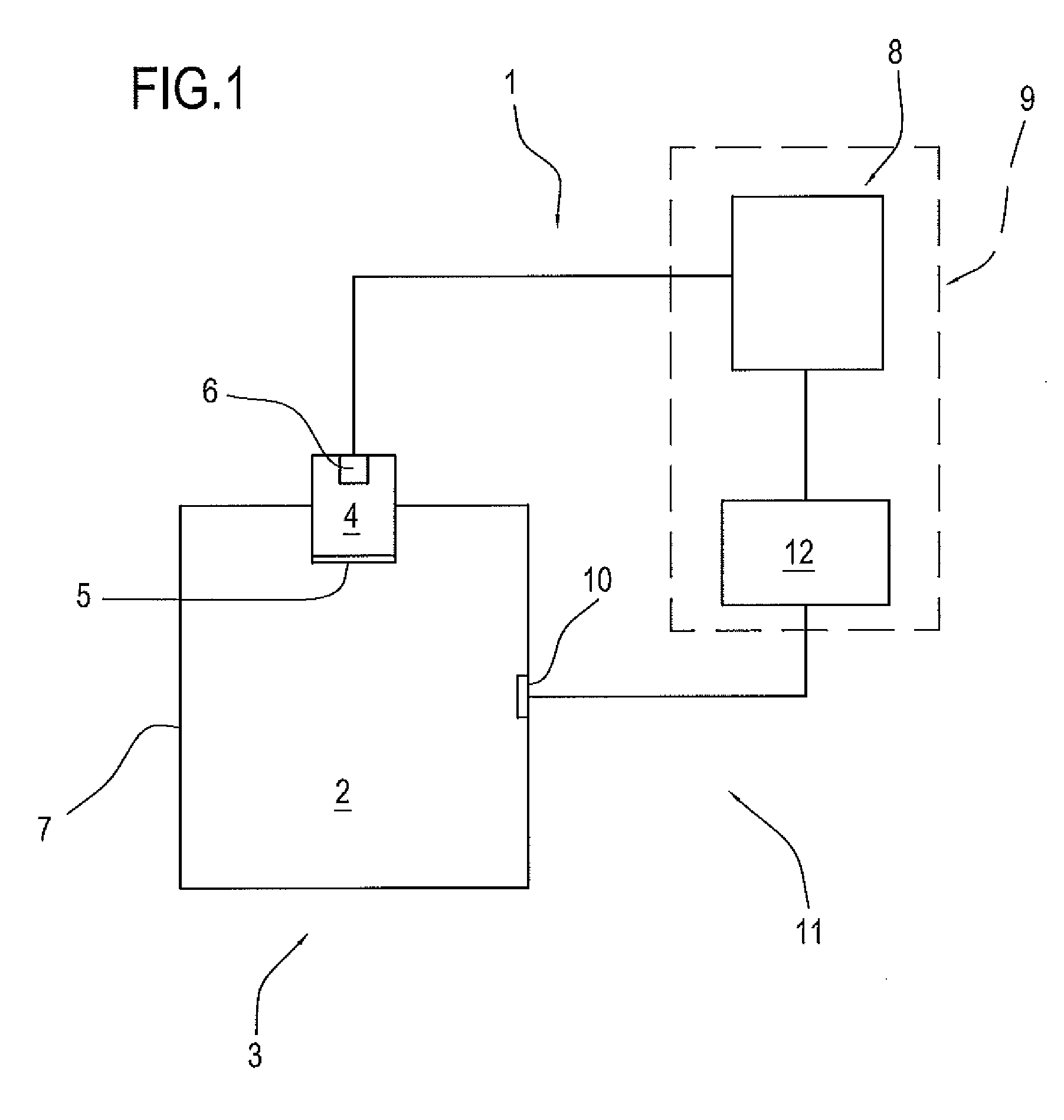
[0045]In the drawings, the numeral 11 denotes a diagnostic apparatus for assessing the insulation condition of electrical equipment 3 insulated with oil 2.

[0046]Generally speaking, the electrical equipment 3 is any electrical equipment (for medium or high voltages) insulated with oil, such as, for example, a transformer, a cable or a switch.

[0047]In particular, however, this invention addresses a diagnostic apparatus for assessing the insulation condition of a transformer insulated with oil.

[0048]Therefore, in the description which follows, the equipment 3 is a transformer.

[0049]This shall not, however, be construed as a limitation of the scope of this invention as the diagnostic apparatus 11 can be associated with other types of electrical equipment, such as, for example, a cable or any electrical equipment insulated with oil.

[0050]The oil 2 of the transformer is held in a container 7, hereinafter referred to as container 7 of the oil 2.

[0051]The diagnostic apparatus 11 is equipped...


PUM


Abstract

A diagnostic method and apparatus for assessing the insulation condition of electrical equipment (3) insulated with oil (2). The method comprises the following steps: measuring the concentration of at least one gas dissolved in the insulating oil (2) of the electrical equipment (3); deriving at least one concentration parameter correlated with the gas concentration measured in a predetermined acquisition time interval; measuring electrical pulses relating to partial electrical discharges which occur in the electrical equipment (3) and which generate said pulses; deriving at least one discharge parameter correlated with the partial discharges measured substantially concurrently with the predetermined acquisition time interval; deriving a diagnostic indication about the insulation condition of the electrical equipment (3) as a function of the derived values of the concentration and discharge parameters.

Description

TECHNICAL FIELD[0001]This invention relates to a diagnostic method and apparatus for assessing the insulation condition of electrical equipment insulated with oil.[0002]More specifically, the invention addresses the field of diagnostic assessment of electrical transformers insulated with oil. In effect, in the field of medium- or high-voltage transformers, oil is frequently used to insulate the transformers.BACKGROUND ART[0003]Diagnostic apparatuses for assessing the insulation condition of transformers (or other medium- or high-voltage equipment) insulated with oil have been in use for some time. These apparatuses are based on a technique known as DGA (dissolved gas analysis), for estimating the concentration of gases dissolved in the oil.[0004]DGA is based on measuring the concentration of predetermined types of gases dissolved in the insulation oil in order to derive a diagnostic indication about the insulation condition of the transformer, that is to say, to derive an indication...

Claims


Application Information

Patent Timeline
IPC IPC(8): G01R31/12G06F19/00
CPCG01R31/1281G01N33/2841G01R31/14G01R31/12
Inventor CAVALLINI, ANDREACIANI, FABIOSERRA, STEFANOMONTANARI, GIAN CARLO
Owner TECHIMP TECHNOLOGIES SA
Learn More