
LED streetlamp installation seat and LED streetlamp

Inactive Publication Date: 2012-11-15
SHENZHEN BANG BELL ELECTRONICS
View PDF17 Cites 36 Cited by
  • Summary
  • Abstract
  • Description
  • Claims
  • Application Information

AI Technical Summary

Benefits of technology

[0004]Taking above into consideration, an object of the present invention is to provide an LED streetlamp installation seat that does not need take down a whole cover cap in the repairing process.
[0005]Another object of the present invention is to provide an LED streetlamp that can ensure a simple and a high work efficiency in an installation process and a repairing process, and a low cost.
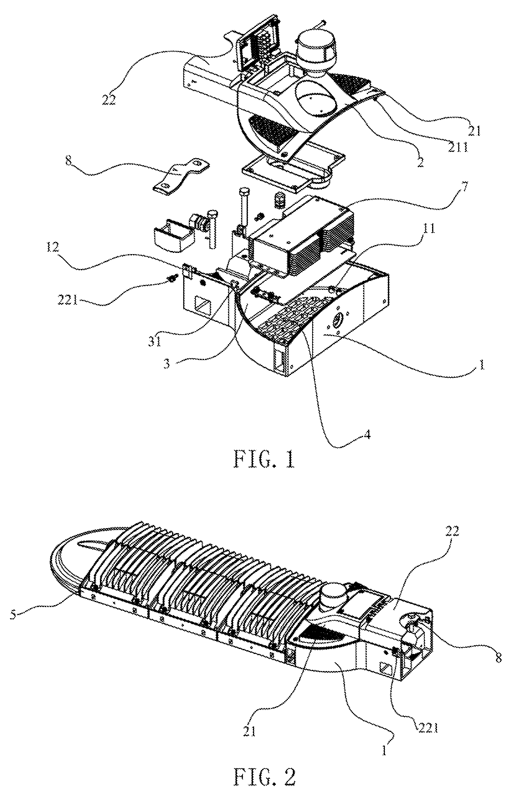
[0021]Comparing to the conventionally technology, the LED streetlamp installation seat of the present invention, utilizes the hinge jointed first cap and the second cap to realize the detachable connection between the first cap and the first accommodating chamber, and the detachable connection between the second cap and the second accommodating chamber. Thus, when the control device needs to be repaired, the first cap can be opened directly through upwardly turning it 90 degrees, relatively to the second cap. Therefore, the electrical power and the PCB can be repaired conveniently. At the end, the operator just need downwardly turn the first cap to the first accommodating chamber. In the whole repairing process, no need of taking down the second cap. Therefore, the repairing process is simple and conveniently, and the efficiency is high. At the same time, in the process of installing LED streetlamp to the lamppost, the operator just needs to loosen the two screws, and upwardly turn the second cap 90 degrees, relative to the first cap. And then, the operator can conveniently fix the fixing device to the lamppost. In the whole installation process, no need of taking down the first cap. Therefore, the installation process is simple and conveniently, and the work efficiency is high. In addition, a plurality of through-holes is provided at a bottom surface of the first accommodating chamber, those can help disperse the heat energy from the control device to the atmosphere. Thus, the heat dispersion efficiency can be enhanced, and the lifespan of the control device can be assured. Furthermore, the first cap and the first accommodating chamber are connected through the cooperation of the strip-shaped blocks and the grooves. Thus, only two screws are needed at the two ends of the first cap and the first accommodating chamber, respectively, for realizing the fixing structure. The second cap and the second accommodating chamber are connected also only through two screws, which can save a lot of screws used at a middle part thereof in conventional technology. Therefore, the LED lamp installation seat can ensure a simple structure and low cost.
[0022]Comparing to the conventional technology, the LED lamp of the present invention can realize a convenient repairing and installation processes, through utilization of the LED streetlamp installation seat as described above. Especially, in the installation process, only the second cap needs to be opened, which is easily to assemble.

Problems solved by technology

In usage, the high voltage sodium lamp has a low optical controllability, low light conversion efficiency, and which produces quite an amount waste of light energy, and a serious light pollution, even though the high voltage sodium lamp has a simply structure and a low cost.
Furthermore, the high voltage sodium lamp has a special problem, which is producing strong glare, which will influence the driving safety.
This process is inconvenient and unsafe for an operator, especially for a steeplejack.
And, a high maintenance fee and low work efficiency is produced at the same time.
Therefore, a large of thermal energy produced by the electrical power and / or the PCB cannot be dispersed to the atmosphere, which will shorten the lifespan of the electrical power and / or the PCB.

Method used


Image

  • LED streetlamp installation seat and LED streetlamp
  • LED streetlamp installation seat and LED streetlamp
  • LED streetlamp installation seat and LED streetlamp

Examples


Embodiment Construction

[0027]Reference will now be made to the drawings to describe preferred and exemplary embodiments in details.

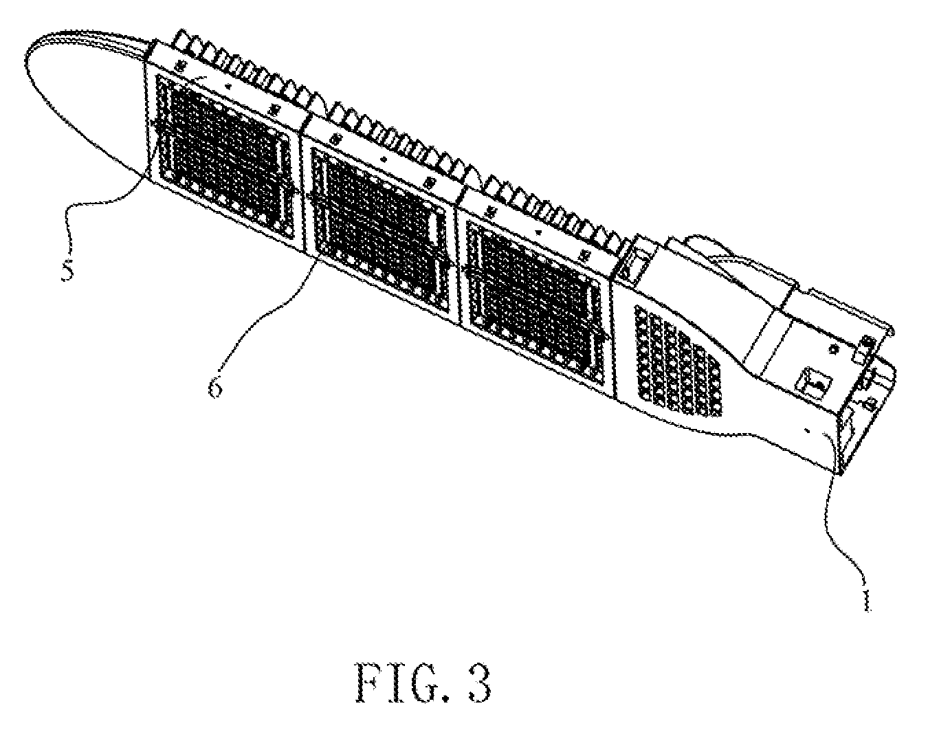
[0028]Referring to FIG. 1, an LED streetlamp installation seat according to an embodiment of the present invention is shown. The LED streetlamp installation seat includes a seat body 1. The seat body 1 includes a first accommodating chamber 11 and a second accommodating chamber 12. The first accommodating chamber 11 accommodates a control device 7, that includes an electrical power and / or a PCB and / or other electrical elements, etc. The control device 7 is used to turn-on or turn-off an LED streetlamp. The second accommodating chamber 12 accommodates a fixing device 8, which is used to connect the LED streetlamp to a lamppost and fix it thereon. The seat body 1 further includes a cover cap 2, disposed at a corresponding position of the first and the second accommodating chambers 11, 12. The cover cap 2 is installed at a top opening of the first and the second accommodating cha...


PUM


Abstract

An exemplary LED streetlamp installation seat and an LED lamp both has a seat body (1), which has a first accommodating chamber (11) and a second accommodating chamber (12) the first accommodating chamber (11) being used to accommodate a control device (7) for controlling the LED streetlamp and the second accommodating chamber (12) being used to accommodate a fixing device (8) for installing the LED lamp to a lamp-post; and a cover cap, corresponding to the first and the second accommodating chambers (11, 12), which has a first cap (21) and a second cap (22), the first cap (21) and the second cap (22) being hinge-joined. The first cap (21), corresponding to the first accommodating chamber (11), is detachably connected to the first accommodating chamber (11). The second cap (22), corresponding to the second accommodating chamber (21), is detachably connected to the second accommodating chamber (21).

Description

FIELD OF THE INVENTION[0001]The present invention relates to an element for an LED (Light Emitting Diode) streetlamp, and more particularly to an LED streetlamp installation seat and an LED streetlamp having the LED streetlamp installation seat.BACKGROUND[0002]For street and road illumination, high voltage sodium lamp is usually used in conventional technology. In usage, the high voltage sodium lamp has a low optical controllability, low light conversion efficiency, and which produces quite an amount waste of light energy, and a serious light pollution, even though the high voltage sodium lamp has a simply structure and a low cost. Furthermore, the high voltage sodium lamp has a special problem, which is producing strong glare, which will influence the driving safety. However, an LED streetlamp can resolve all the above-described problems.[0003]A conventional LED streetlamp generally includes a frame, an LED lighting module disposed on the frame. For fixing the LED streetlamp on one...

Claims


Application Information

Patent Timeline
IPC IPC(8): F21S8/08
CPCF21V21/116F21Y2101/02F21W2131/103F21Y2115/10
Inventor HE, LINPAN, PULIANLI, SHENGYUANLI, JIAN
Owner SHENZHEN BANG BELL ELECTRONICS
Learn More