
Shaft-gear connection

a technology of gear teeth and shafts, applied in the direction of couplings, manufacturing tools, transportation and packaging, etc., can solve the problems of affecting the operation of the gear teeth, the gear teeth are not prevented, and the components are moving, so as to achieve the effect of preventing damage to the gear teeth

Inactive Publication Date: 2012-11-08
ZF FRIEDRICHSHAFEN AG
View PDF4 Cites 10 Cited by
  • Summary
  • Abstract
  • Description
  • Claims
  • Application Information

AI Technical Summary

Benefits of technology

[0010]The basic object of this invention is therefore to create a shaft-gear connection with a shaft and a shrunk-fit gear that enables the transmission of a great torque from the gear to the shaft, while at the same time effectively preventing damage to the gear teeth. A further object of the invention is also to propose a method of manufacturing this kind of advantageous shaft-gear connection.

Problems solved by technology

The types of known connections described above are characterized by the disadvantage that movement of the components or, as the case may be, the gears on the shaft is not prevented.
Despite optimized design, microscopic movements do occur, for example, due to load peaks.
In the worst possible case, this multi-axial stress-state can lead to a break in one or more of the gear teeth of the cogging.
This measure has the disadvantage, however, of reducing the maximum torque that can be transmitted from the gear to the shaft.

Method used


Image

  • Shaft-gear connection
  • Shaft-gear connection
  • Shaft-gear connection

Examples


Embodiment Construction

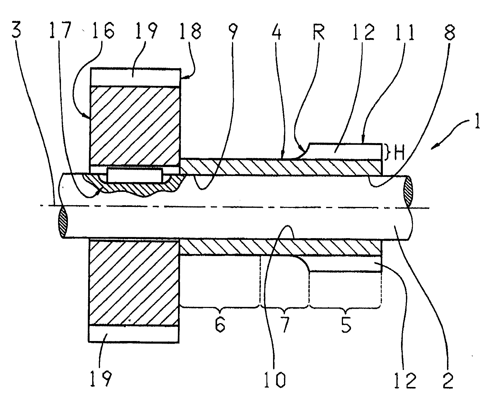
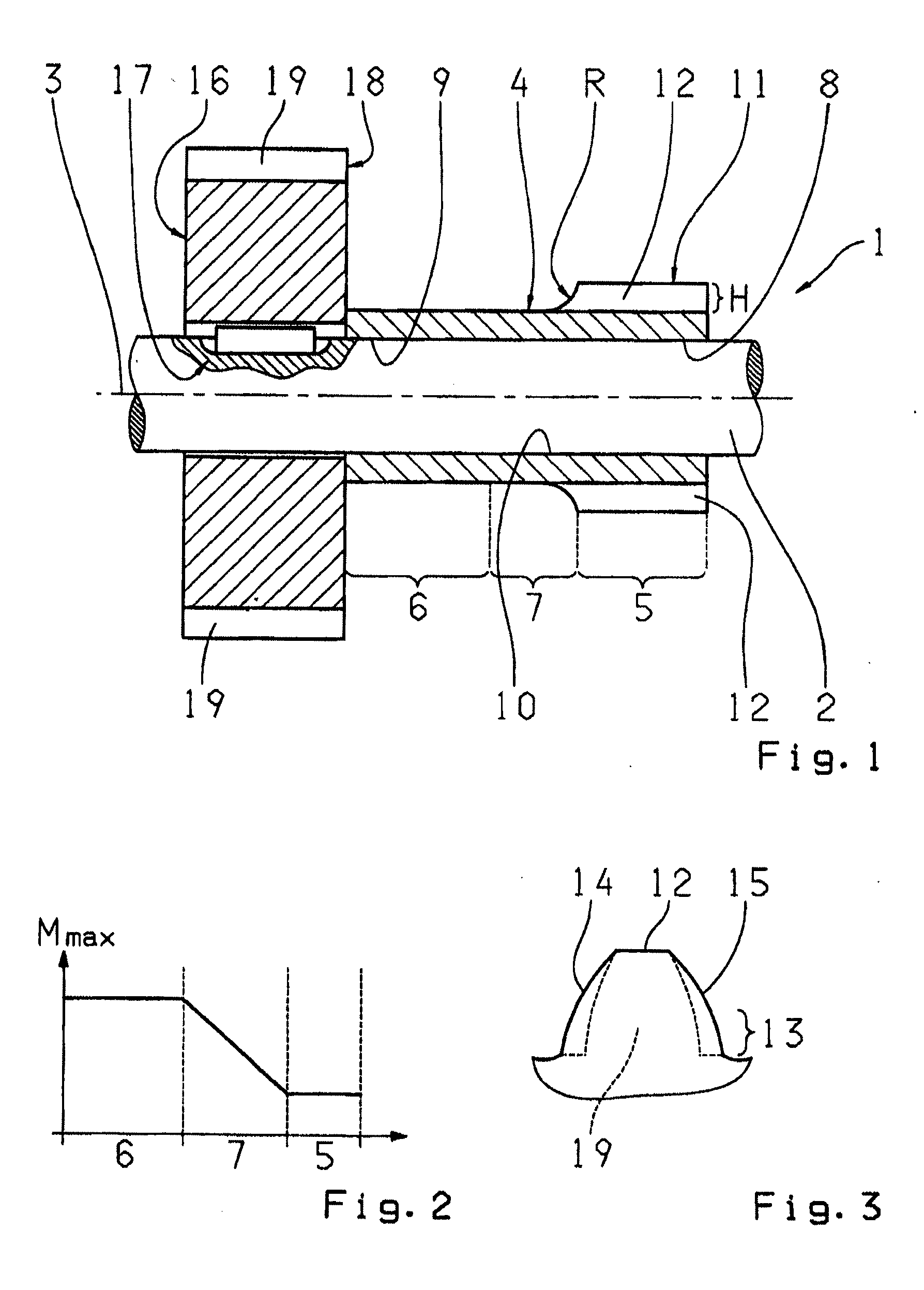
[0036]FIG. 1 presents a lateral view of an embodiment of the inventive shaft-gear connection 1. To start with, the shaft-gear connection 1 comprises a shaft 2 that is rotatable around a longitudinal axis 3 thereof. A gear 4 is shrunk-fit to the shaft 2 so as to permanently and constantly rotate with the shaft 2. The gear 4 comprises an axial first section 5 and an axial second section 6, and an intermediate section 7 is provided between the axial first section 5 and the axial second section 6. The first, intermediate and second sections referred to as 5, 7, 6 are integral with and directly attached to one another to form a single, unitary component. The first section 5 has an axial length L5 of typically between 30 mm and 80 mm; the second section 6 has an axial length L6 of typically between 20 mm and 60 mm; and the intermediate section 7 has an axial length L7 of typically between 5 mm and 30 mm.

[0037]The axial first section 5 is attached to the shaft 2 by a first shrink-fit 8, wh...


PUM

PropertyMeasurementUnit
Diameteraaaaaaaaaa
Heightaaaaaaaaaa
Surface pressureaaaaaaaaaa

Abstract

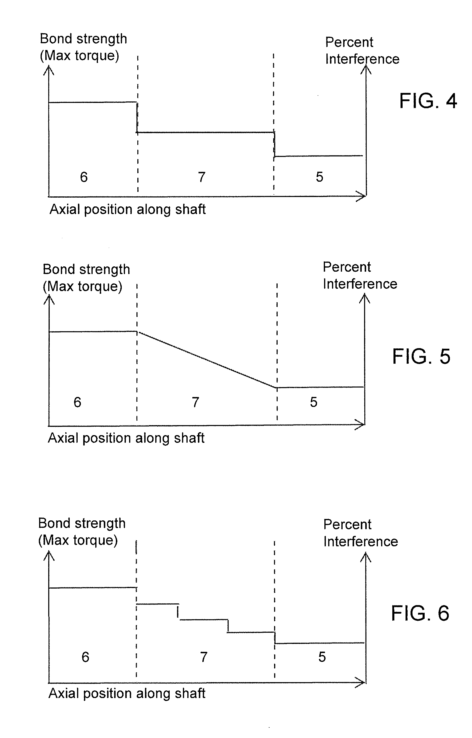
A shaft-gear connection comprises a shaft and a shrunk-on gear that has an axial first section, attached by a first shrink-fit bond, and an axial second section, attached by a second shrink-fit bond. The second shrink-fit bond is greater than the first shrink-fit bond so that a greater maximum torque to be transmitted from the gear to the shaft by the second shrink-fit bond than by the first shrink-fit bond. An axial intermediate section, attached by a third shrink-fit bond, is located between the axial first section and the axial second section. Both a surface pressure and a maximum torque that can be transmitted by the third shrink-fit bond are greater than the surface pressure and the maximum torque that can be transmitted by the first shrink-fit bond, but are less than the surface pressure and the maximum torque that can be transmitted by the second shrink-fit bond.

Description

[0001]This application is a continuation-in-part of U.S. patent application Ser. No. 12 / 447,697 filed on Apr. 29, 2009, which is a National Stage completion of PCT / EP2007 / 060883 filed Oct. 12, 2007, which claims priority from German patent application serial no. 10 2006 052 104.8 filed Nov. 4, 2006.FIELD OF THE INVENTION[0002]The invention relates to a shaft-gear connection comprising a shaft and a shrunk-on gear. The shrunk-on gear has an axial first section that is attached to the shaft by means of a first shrink-fit and an axial second section that is attached to the shaft by means of a second shrink-fit. The second shrink-fit allows greater torques to be transmitted from the gear to the shaft than with the first shrink-fit. The invention also relates to a method for producing such a gear-shaft connection.BACKGROUND OF THE INVENTION[0003]Shafts that transmit torques and have gears arranged on the shafts are very common in transmission manufacturing. There are a large number of op...

Claims


Application Information

Patent Timeline
IPC IPC(8): F16B4/00B23P15/14B23K20/12
CPCF16D1/0858Y10T403/48Y10T29/49462
Inventor HARDTLE, WILHELM
Owner ZF FRIEDRICHSHAFEN AG
Learn More