
Method and system for structural analysis of an object by measuring the wave front thereof

a technology of wave front and wave front, applied in the field of structural analysis of objects, can solve the problems of inability to extract inability to be compatible with in vivo observations of biological tissues, and inability to achieve phase information of the field diffracted by the obj

Inactive Publication Date: 2012-11-01
PHASICS +2
View PDF4 Cites 2 Cited by
  • Summary
  • Abstract
  • Description
  • Claims
  • Application Information

AI Technical Summary

Benefits of technology

[0023]A wavefront analyser according to the invention is an apparatus that enables the scalar electromagnetic field of a light wave to be measured, i.e. that measures both its phase and its intensity. Because of its nature, it is self-referenced, the beam received serves as a reference to itself. It therefore has the advantage of not requiring a reference beam and of being insensitive to vibrations.
[0025]The adaptation of the spatial coherence of the generating and receiving means is intended to provide spatially coherent light at the level of the receiving means. Indeed, wavefront analysis technologies use theories based on point light sources, said to be spatially coherent. When the light source is no longer a point light source, the analyser captures a superposition of waves, which has two effects. First, the measurement is less precise because the marginal points of the source disrupt the measurement at the centre of the source. Second, each of the points of the source will be diffracted differently by the object. Thus, the information necessary for measuring the complex electromagnetic field is diluted between the different points of the source. To perform such a spatial coherence adaptation, it is possible to envisage, according to the invention, providing a device for filtering the spatial coherence of the wave generated by the light source.
[0026]By combining diffraction tomography and wavefront analysis technologies, the invention therefore makes it possible to solve the aforementioned technical problem, while providing sufficient lateral resolution to benefit from high imaging quality.

Problems solved by technology

Nevertheless, because of the use of X-rays, which requires placing the samples under vacuum, this solution is not compatible with in vivo observations of biological tissues.
The number of potential applications of X-ray imaging is therefore limited.
However, this principle, based on intensity measurements, does not enable the phase information of the field diffracted by the object to be extracted.
The general problem addressed in the field of optical tomography concerns the three-dimensional reconstruction of the complex refraction index of a sample.
The vertical scanning microscopy systems do not enable, in the general case, the three-dimensional reconstruction of the complex refraction index of an object to be analysed.
First, they involve the use of sources with high temporal coherence, such as lasers.
Then, there are problems of parasitic reflections and speckle effects, which have a detrimental effect on the 2D or 3D measurements.
In addition, they require the use of a reference path, which produces significant structural complications.
These methods are not therefore transposable to the field of microscopy, in which the level of detail is on the order of the resolution of the imaging system.
Thus, none of the prior art solutions makes it possible to provide a tomography system by photon imaging limited by the resolution of imaging systems, eliminating the problems of parasitic reflections and speckle effects, while being structurally simple and compact.

Method used


Image

  • Method and system for structural analysis of an object by measuring the wave front thereof
  • Method and system for structural analysis of an object by measuring the wave front thereof
  • Method and system for structural analysis of an object by measuring the wave front thereof

Examples


first embodiment

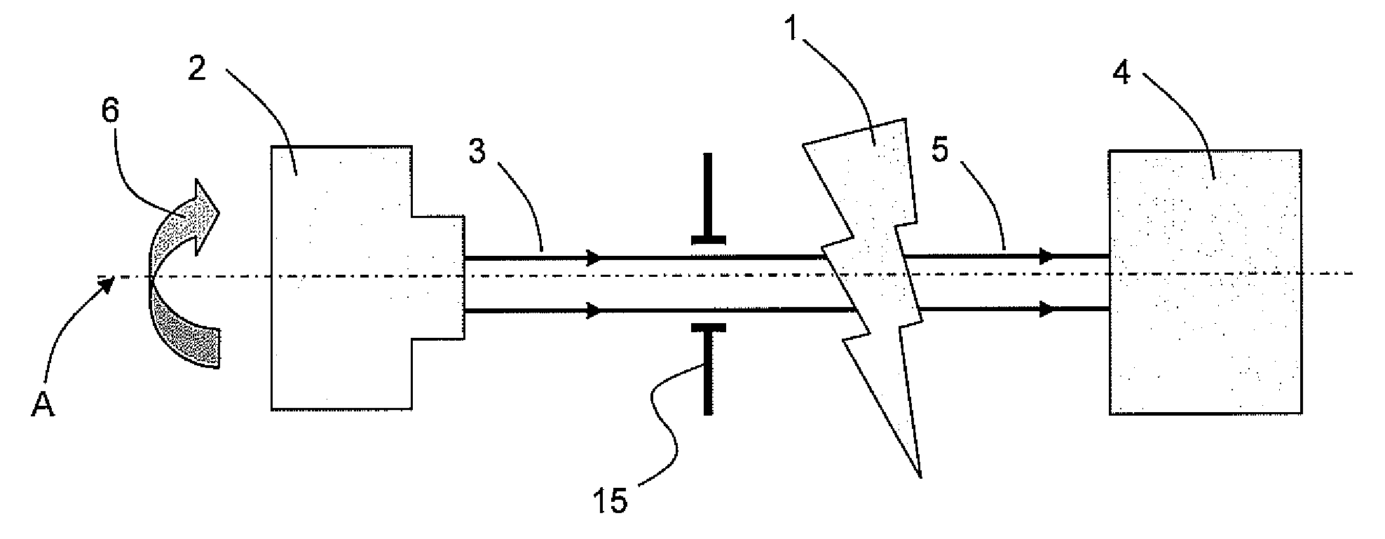
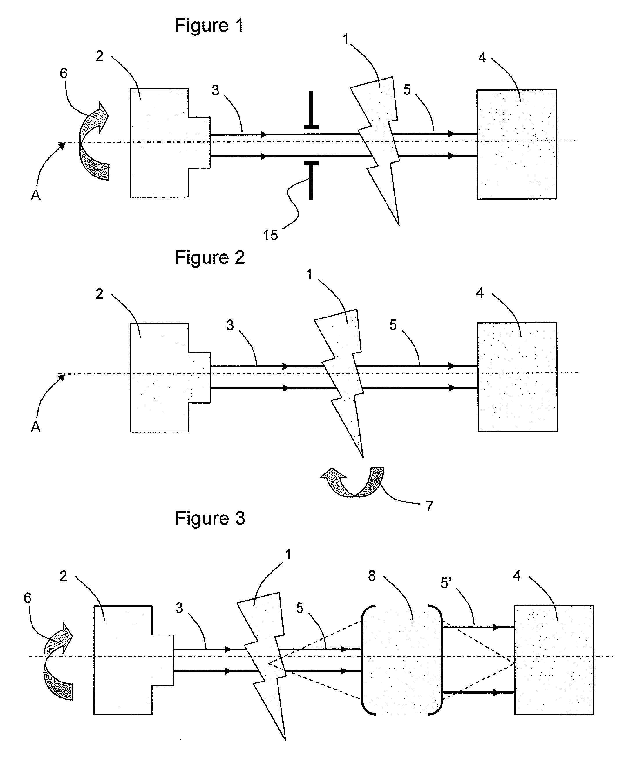
[0056]In reference to FIG. 1, a structural analysis system according to the invention includes means 2 for generating an input light beam 3. This light beam is directed onto a portion of the object 1 to be analysed. Receiving means 4 enable the output light beam 5, resulting from the interaction between the input beam 3 and the object 1, to be recovered.

[0057]The object 1 is the subject of the tomographic analysis. The objective is, in this case, to reconstruct this object three-dimensionally, by an optical transmission measurement, according to a three-dimensional tomographic optical microscopy principle. This method is intended to provide a dimensional characterisation of the object or sample, via a preliminary measurement of its shape and permittivity distribution, with quantitative measurement results.

[0058]The object 1 is, in this case, an object having some transparency, so that the receiving means 4 can recover a portion of the light flux generated by the means 2 after intera...

second embodiment

[0081]In the second embodiment, in reference to FIG. 2, the means 2 for generating the incident beam 3 are fixed so that the beam 3 is parallel to the optical axis. The means for orienting the interaction 7 are now the means for rotating the sample with respect to the optical axis A. Since the source 2 is arranged so that the incident beam 2 is perpendicular to the optical axis, a tilt of the incident beam 3 with respect to the surface of the sample is derived therefrom, as it is seen by the analyser 4.

[0082]In the third embodiment, in reference to FIG. 3, the means for orienting the interaction 6 are identical to those of the first embodiment. The means 8 for optical conjugation are arranged between the object 1 and the receiving means4. These means 8 include a lens assembly, in order to conjugate the surface of interaction of the object 1 with the plane of the sensor integrated with the wavefront analyser 4, thereby notably improving the measurement results.

[0083]In the fourth emb...

eighth embodiment

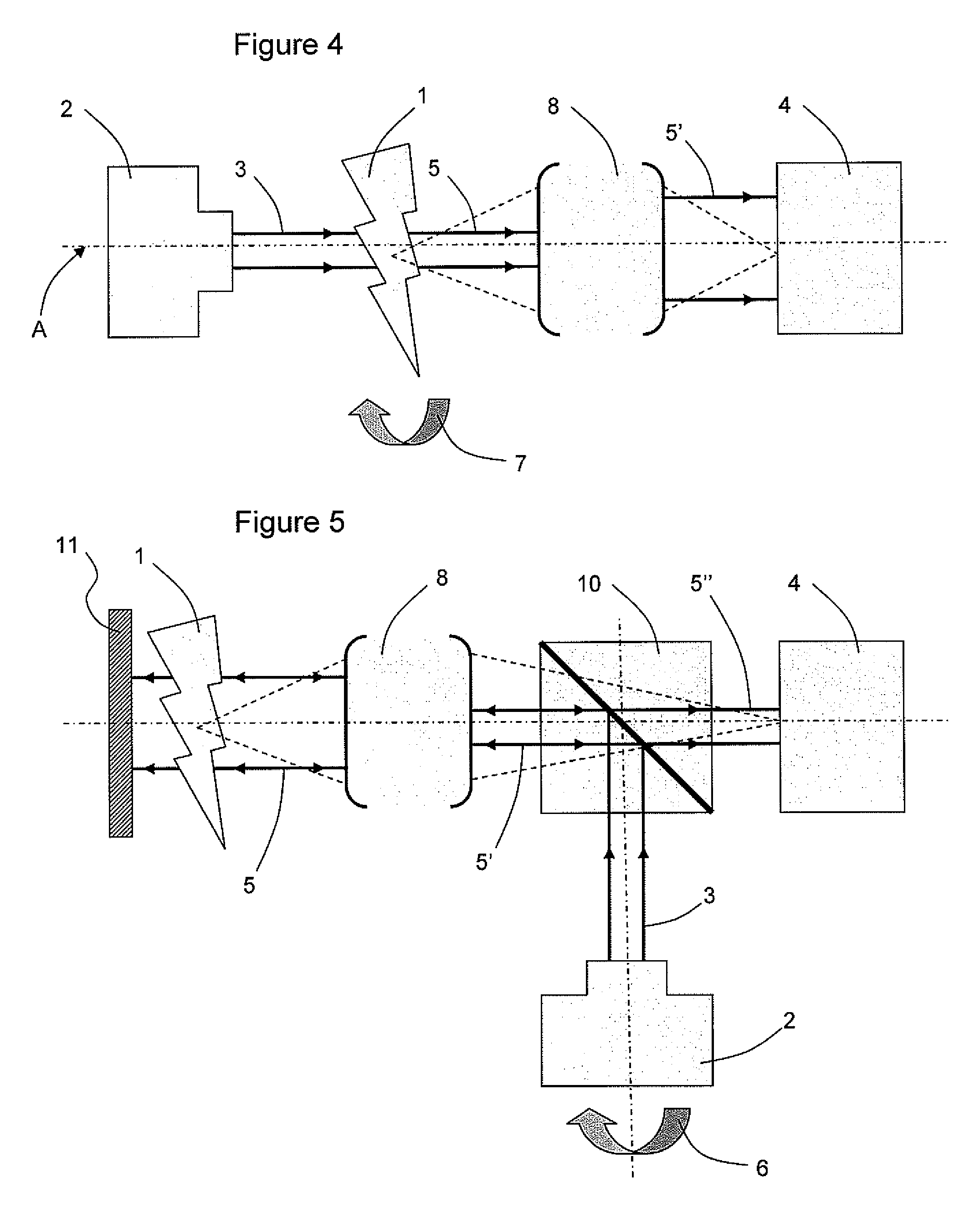
[0092]The eighth embodiment, in reference to FIG. 8, presents the case in which the object is entirely reflective and does not therefore have any transparency. In this case, it, by itself, constitutes the reflective element and it is not necessary to use a mirror in order to produce the back-reflection (as described above in reference to FIG. 5). The measurement obtained is then a surface topology.

[0093]More specifically, the source 2 is arranged in order to direct the incident beam 3 that it generates in the direction of the reflective object 1. Means 6 for orienting this source 2 make it possible to cause the angle of incidence of the beam 3 on the surface of the object 1 to be varied. Therefore, the diffracted and reflected beam 5, resulting from the interaction between the beam 3 and the object 1, is received by the receiving means integrating the wavefront analyser 4. For this, the source 2 and the sensor 4 must be on the same side of the object 1. One option thus consist of ti...


PUM


Abstract

A system for structural analysis of an object, including a device for generating an input light beam arranged so as to cause the input beam generated to interact with at least one portion of the object, and a device for receiving the output light beam resulting from the interaction between the input beam and the object. In this system, the receiving device include a wavefront analyzer arranged so as to measure the electromagnetic field of the wave of the output beam received, and the generating device has a spatial coherence adapted to that of the receiving device. A structural analysis method implementing such a system is presented.

Description

BACKGROUND[0001]1. Technical Field[0002]This invention relates to the field of structural analysis of objects. This type of metrological analysis consists of optical tomography enabling the surface topology of opaque objects to be determined or the volume of transparent objects to be reconstructed. It is thus capable of being applied, in particular, in biological and medical fields (tomography of cells, skin) and materials (tomography of structured materials, reading of invisible 3D structures such as impurities, memories, counterfeit products).[0003]It relates more specifically to a system for structural analysis of an object, including means for generating an input light beam, arranged to cause the input beam generated to interact with at least one portion of the object, and means for receiving the output light beam resulting from the interaction between the input beam and the object.[0004]It also relates to a method for structural analysis of an object, including a step of genera...

Claims


Application Information

Patent Timeline
IPC IPC(8): G01B11/24
CPCG01N21/4795
Inventor BON, PIERREWATTELLIER, BENOITMONNERET, SERGEGIOVANINI, HUGUESMAIRE, GUILLAUME
Owner PHASICS
Learn More