
Flame trap cartridge, flame arrestor, method of preventing flame propagation into a fuel tank and method of operating an aircraft

Inactive Publication Date: 2012-11-01
AIRBUS OPERATIONS LTD
View PDF6 Cites 40 Cited by
  • Summary
  • Abstract
  • Description
  • Claims
  • Application Information

AI Technical Summary

Benefits of technology

[0024]Providing a foam component provides a series of channels in a similar way to the prior art flame trap cartridges made of crimped stainless steel. However, the foam component is able to be cut, machined, or otherwise made, into a wide variety of different shapes and sizes and so can be located in, or in a portion of, a vent passage or flame arrestor that is not of a uniform shape. In addition, the foam component provides a series of non-uniform channels that force a flame to change direction as it attempts to pass through. It is believed that such a feature enhances the flame resistance properties of the foam, compared to having linear channels. Hence, the resistance time of the foam is increased, in comparison to prior art crimped metal flame trap cartridges. This can be done without substantially narrowing the channels (or pores / cells) in the flame trap cartridge and so without substantially adversely affecting the passage of fuel though the vent passage during refuel overflow.
[0031]Preferably, the foam component comprises a skeletal foam structure. For example, the foam component may be substantially incompressible. A skeletal foam typically has a very low density (about 10%) and a very high void volume (about 90%). These characteristics mean that for a similar size of crimped stainless steel prior art flame trap cartridge, the flame trap cartridge according to an embodiment of the present invention can be much lighter and provide less of a restriction during refuel overflow.
[0037]Preferably, the foam component is a non-uniform shape. This allows the flame trap cartridge to be used in a vent passage and / or flame arrestor with a non-uniform shape. For example, a flame trap cartridge according to an embodiment of the present invention could be used in a curved portion of a vent passage. This allows the flame trap cartridge to be used in aircraft wings, for example, where space is limited. Preferably, the foam component is provided with at least one curved portion along the axis between the two opposite ends. This allows the foam component to fit in a curved portion of a vent passage. Preferably, the foam component has a varied diameter between the two opposite ends. This allows the foam component to fit in a portion of a vent passage with a varied diameter, for example, a converging or diverging vent passage.
[0041]Providing a foam component provides a series of channels in a similar way to the prior art flame arrestors. However, the foam component is able to be cut, machined, or otherwise made, into a wide variety of different shapes and sizes and so can be located in, or in a portion of, a vent passage that is not of a uniform shape. In addition, the foam component provides a series of non-uniform channels that force a flame to change direction as it attempts to pass through. It is believed that such a feature enhances the flame resistance properties of the foam, compared to having linear channels. Hence, the resistance time of the foam is increased, in comparison to prior art flame arrestors containing crimped metal flame trap cartridges. This can be done without substantially narrowing the channels (or pores / cells) in the flame arrestor and so without substantially adversely affecting the passage of fuel though the vent passage during refuel overflow.
[0044]According to a third aspect of the invention there is also provided a method of preventing flame propagation into a fuel tank, the method comprising the steps of providing a fuel tank, providing a vent passage for fuel or fuel vapour from the fuel tank, providing the vent passage with foam material.

Problems solved by technology

However, the foam component is able to be cut, machined, or otherwise made, into a wide variety of different shapes and sizes and so can be located in, or in a portion of, a vent passage or flame arrestor that is not of a uniform shape.
In addition, the foam component provides a series of non-uniform channels that force a flame to change direction as it attempts to pass through.

Method used


Image

  • Flame trap cartridge, flame arrestor, method of preventing flame propagation into a fuel tank and method of operating an aircraft
  • Flame trap cartridge, flame arrestor, method of preventing flame propagation into a fuel tank and method of operating an aircraft
  • Flame trap cartridge, flame arrestor, method of preventing flame propagation into a fuel tank and method of operating an aircraft

Examples


Embodiment Construction

[0062]FIG. 5 shows a perspective view of a flame trap cartridge 154 according to a first embodiment of the invention. The flame trap cartridge 154 is for use in a flame arrestor, such as that described in relation to FIGS. 1 to 4, instead of prior art flame trap cartridge 54.

[0063]The flame trap cartridge 154 is a cylindrical disc with a circular casing 160 around its side edge circumference. Inside the casing 160 is a foam component 170 comprising reticulated foam material.

[0064]An enlarged view of the reticulated foam material 170 is shown in FIG. 6. FIG. 7 is a schematic drawing of a reticulated foam cell structure. Here, it can be seen that the cell structure comprises cells 171 formed where ligaments 172 join. Each cell 171 comprises a number of pores 173 in the cell. The pores 173 have a diameter of approximately 1.8 mm.

[0065]FIG. 8 shows a schematic drawing of a truncated octahedron reticulated cell 174. Here, the cell 174 is a truncated octahedron shape with 14 faces 175. Th...


PUM


Abstract

The invention provides a flame trap cartridge 154 for use in a flame arrestor 50, the flame trap cartridge comprising a casing 160, and a foam component 170 having two opposite ends and at least one side edge, wherein the foam component is at least partially encased around at least one side edge by the casing. The invention also provides a flame arrestor, a method of preventing flame propagation into a fuel tanks and a method of operating an aircraft.

Description

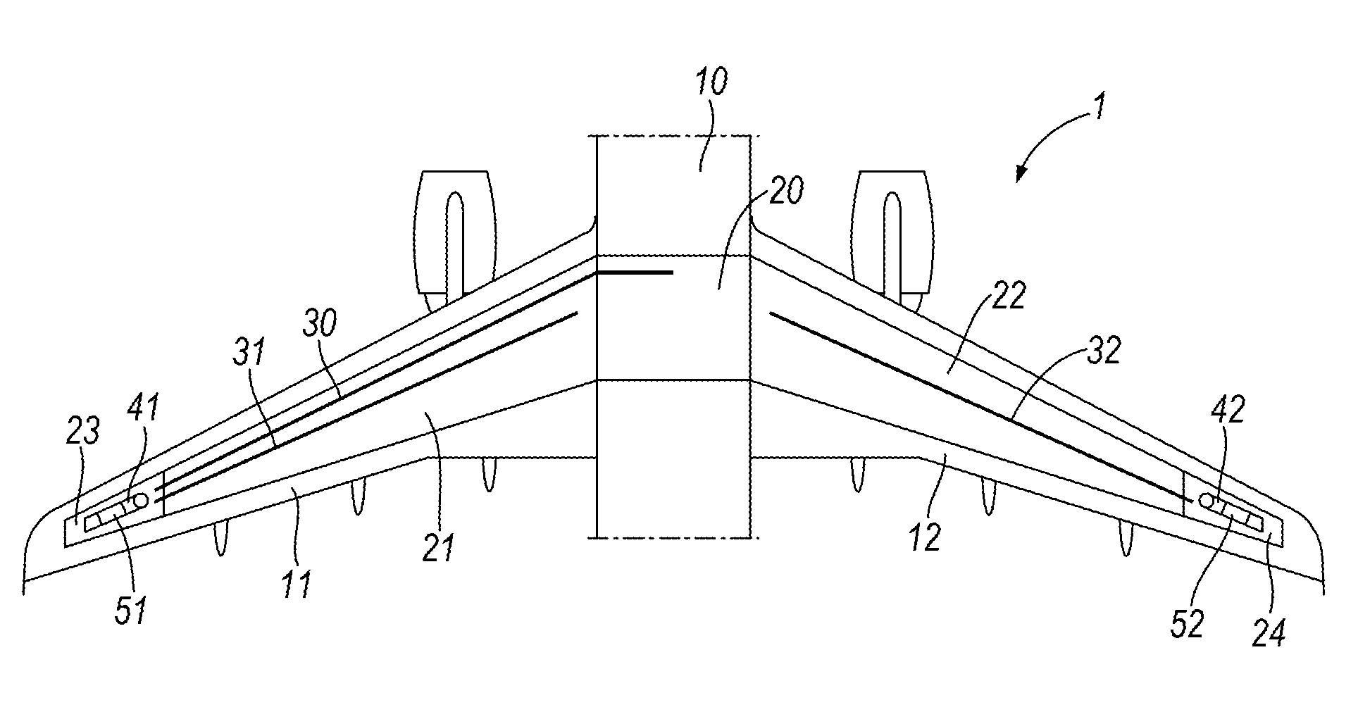
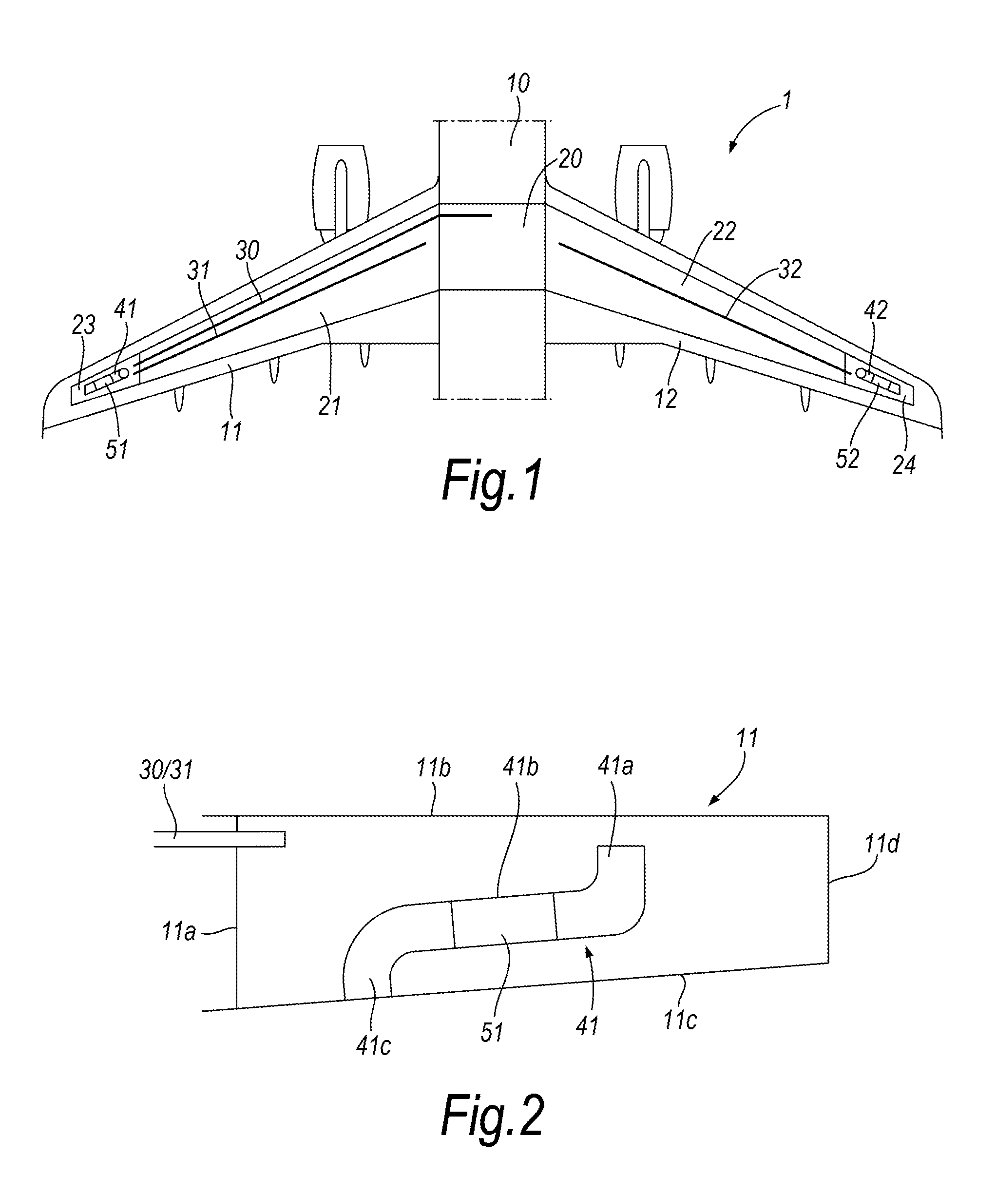
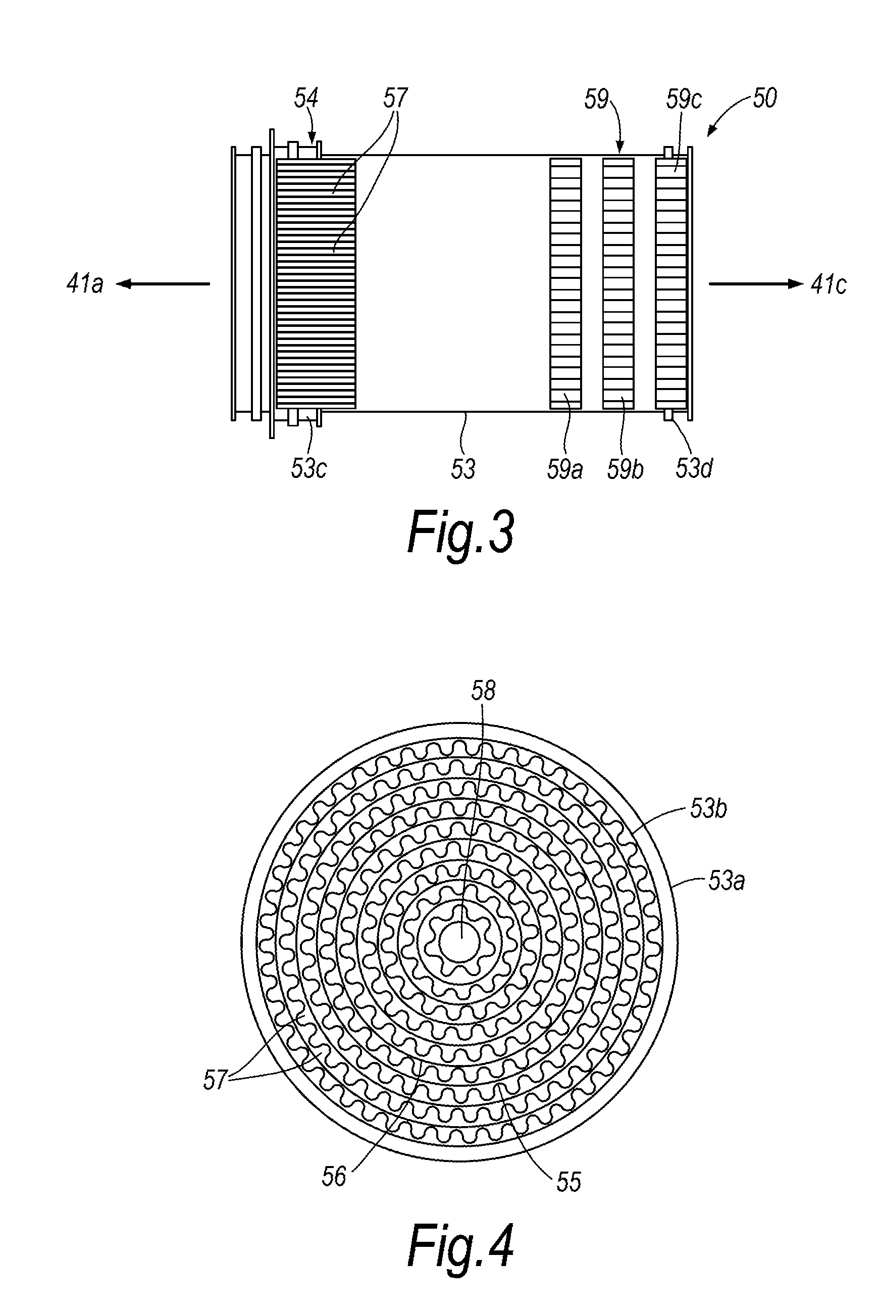
BACKGROUND OF THE INVENTION[0001]The present invention concerns flame trap cartridges. More particularly, this invention concerns flame trap cartridges for use in a flame arrestor or vent passage of an aircraft. The vent passage may be associated with a fuel tank of an aircraft. The fuel tank may be a main storage tank, an auxiliary tank, a surge tank or a vent tank. More particularly, the invention concerns flame trap cartridges comprising a casing.[0002]Typical flame arrestors are located outboard in an aircraft wing, as shown in FIGS. 1 and 2. FIG. 1 shows a partial view of an aircraft 1 with a fuselage 10, port wing 11 and starboard wing 12. The fuselage 10 contains a fuselage fuel tank 20 in between the wings. The port wing 11 contains a port wing tank 21 and the starboard wing contains a starboard wing tank 22. At the outboard end of each wing is a surge tank. 23 designates the port surge tank and 24 designates the starboard wing surge tank.[0003]The port wing tank 21 is provi...

Claims


Application Information

Patent Timeline
IPC IPC(8): A62C3/08F23D14/82
CPCA62C4/00F23K5/16B64D37/32B33Y80/00
Inventor BRENNAN, SUSAN
Owner AIRBUS OPERATIONS LTD
Learn More