
Valve device

Active Publication Date: 2012-11-01
JTEKT CORP
View PDF6 Cites 2 Cited by
  • Summary
  • Abstract
  • Description
  • Claims
  • Application Information

AI Technical Summary

Benefits of technology

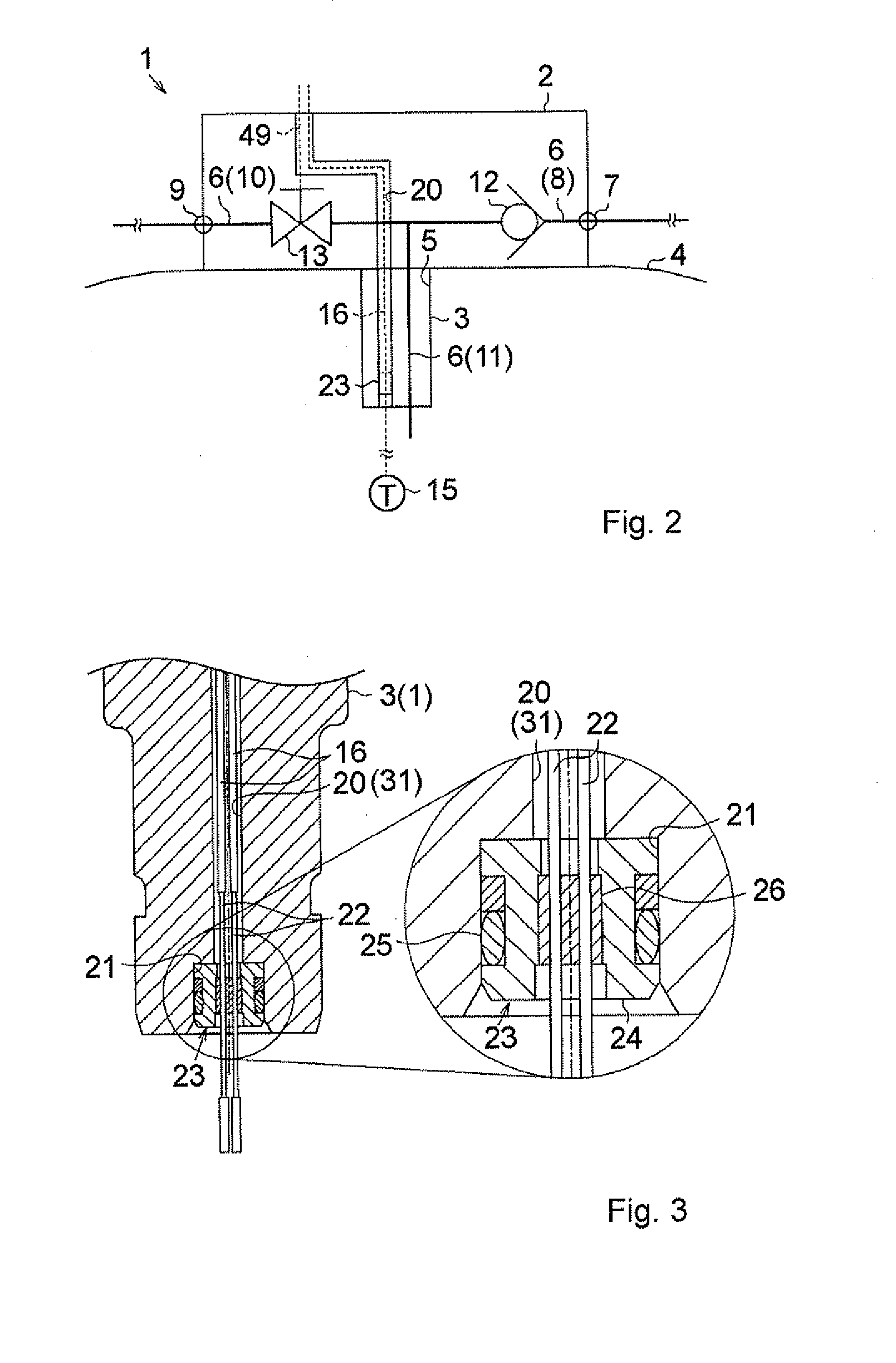
[0011]Even when pulling force acts on the wire from the outside, the stress concentration portion is formed on the outer side of the hermetic connector. Therefore, the force that acts on the wire pin in accordance with the pulling force, that is, the force that pulls the wire pin out of a portion of the hermetic connector, in which the sealing member is provided is reduced. As a result, it is possible to effectively prevent the wire pin from coming out of the hermetic connector with a simple configuration.
[0015]Forming the bent portion in the wire channel makes it difficult to pass the wire through the wire channel. However, the lid member is provided to allow the bent portion to be exposed to the outside. Therefore, it is possible to easily carry out the work for passing the wiring through the wire channel.
[0017]The accommodation chamber for the valve mechanism is utilized as a work space for passing the wire through the wire channel. As a result, it is possible to further easily carry out the work for passing the wire through the wire channel. In addition, when the valve mechanism is a solenoid valve, a power supply wire for the solenoid valve together with the wire is drawn to the outside of the body through the wire channel. Thus, it is possible to simplify the configuration by, for example, omitting a seal member (grommet), and reduce the cost.

Problems solved by technology

Therefore, if wires are pulled from the outside with excessive force, wire pins may be pulled out of a portion of the hermetic connector, at which the sealing member is arranged, by the pulling force.

Method used


Image

  • Valve device
  • Valve device
  • Valve device

Examples


Embodiment Construction

[0027]Hereafter, embodiments of the invention will be described with reference to the accompanying drawings.

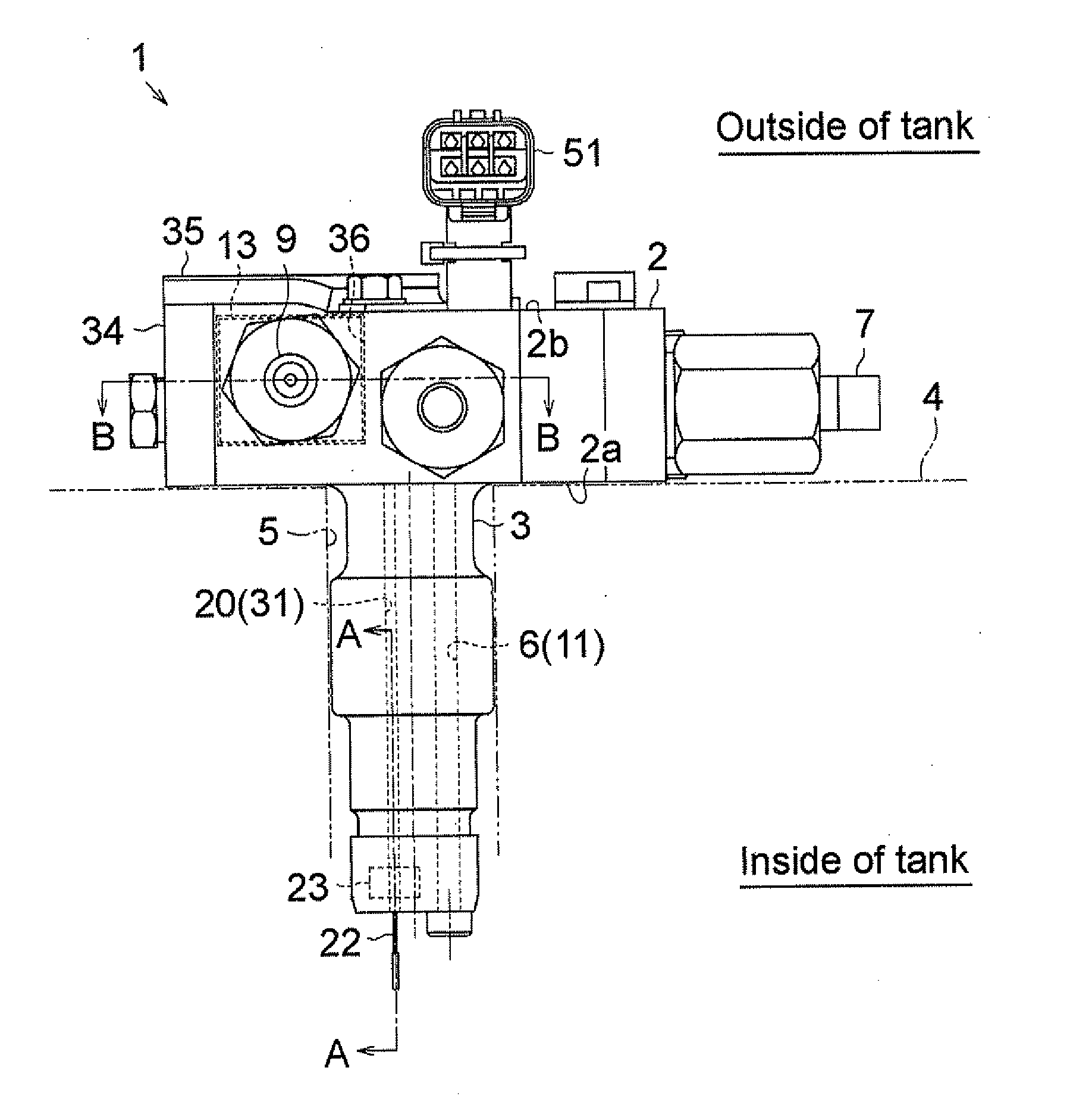
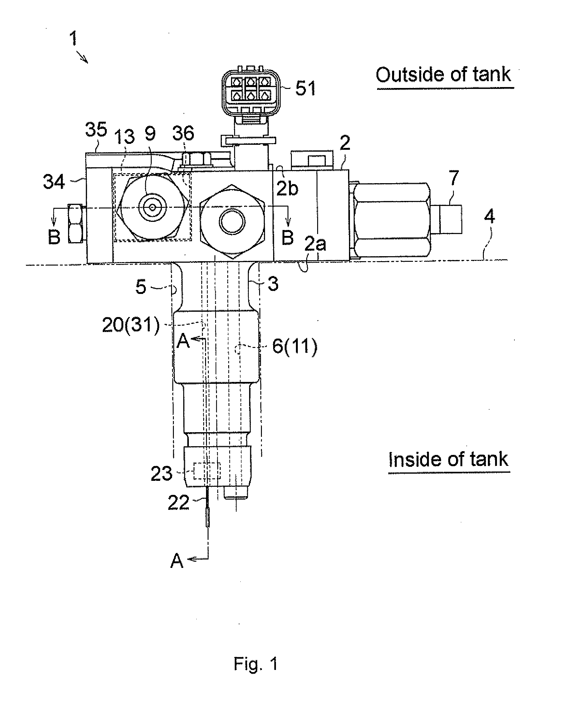
[0028]As shown in FIG. 1, a valve device 1 according to an embodiment includes a substantially box-shaped tank-outside arranged portion 2, and a substantially circular cylindrical tank-inside arranged portion 3. The tank-inside arranged portion 3 extends in a direction substantially perpendicular to a bottom face 2a of the tank-outside arranged portion 2 (downward in FIG. 1). The valve device 1 is fitted to a gas tank 4 in such a manner that the tank-inside arranged portion 3 is installed in an installation port 5 of the gas tank 4 that stores high-pressure hydrogen gas.

[0029]As shown in FIG. 2, the valve device 1 has a gas passage 6 that provides communication between the inside and outside of the gas tank 4. A valve mechanism is provided in an intermediate portion of the gas passage 6. The valve mechanism controls the flow rate of high-pressure hydrogen gas delivered through...


PUM


Abstract

A valve device includes a wire channel through which wires are routed from the inside of a gas tank to the outside of the gas tank, and a hermetic connector in which a sealing member is provided around wire pins that constitute part of the wires is provided in the wire channel. In addition, the wire channel has multiple (two) bent portions formed on the outer side of the hermetic connector. When pulling force acts on the wires from the outside, stress concentration portions are formed in the wires at these bent portions.

Description

INCORPORATION BY REFERENCE / RELATED APPLICATION[0001]This application claims priority to Japanese Patent Application No. 2011-098242 filed on Apr. 26, 2011 the disclosure of which, including the specification, drawings and abstract, is incorporated herein by reference in its entirety.BACKGROUND OF THE INVENTION[0002]1. Field of the Invention[0003]The invention relates to a valve device that includes a wire channel through which a wire is routed from the inside of a tank to the outside of the tank.[0004]2. Discussion of Background[0005]Usually, a valve device fitted to a high-pressure gas tank includes a gas passage that provides communication between the inside of a gas tank and the outside of the gas tank, and a valve mechanism that controls the flow rate of high-pressure gas delivered through the gas passage. For example, a valve device described in US 2003 / 0151018 includes a solenoid valve that serves as a valve mechanism used to control gas supply. In this valve device, a power s...

Claims


Application Information

Patent Timeline
IPC IPC(8): F16K17/00
CPCF17C13/04F17C2205/0326F17C2205/0332F17C2205/0385Y02E60/321F17C2223/035F17C2225/035F17C2250/0439F17C2260/044F17C2221/012F16K1/00F16K31/00F16K31/06F17C2205/0335F17C2223/0123F17C2223/036Y02E60/32Y10T137/1624Y10T137/8158Y10T137/8376
Inventor NUMAZAKI, KAZUSHIIMOTO, YOSHINORIINADA, YUTAKASUZUKI, HIROAKI
Owner JTEKT CORP
Learn More