
Systems and methods for particle detection

a particle detection and system technology, applied in the field of systems and methods for particle detection, can solve the problems of limited use, bulky and expensive instruments, and potential threats to health and environment of nanoparticles generated by vehicles and industries

Active Publication Date: 2012-10-25
WASHINGTON UNIV IN SAINT LOUIS
View PDF61 Cites 26 Cited by
  • Summary
  • Abstract
  • Description
  • Claims
  • Application Information

AI Technical Summary

Problems solved by technology

Meanwhile, nanoparticles generated by vehicles and industry have become recognized as potential threats to health and environment.
However, their widespread use has been limited by bulky and expensive instrumentation, long processing time, and / or the need for labeling.
Light scattering techniques, while suitable for label-free detection, are hindered by the extremely small scattering cross-sections of single nanoparticles.
At least some known particle detection systems use conventional microscopic techniques which, despite their high sensitivity and resolution, may not be suitable for field measurements due to their expensive and bulky constructions, long processing times, and the necessity of pretreatment (labeling with fluorescent dyes, etc.) of the particles.
These sensors generally require a fiber taper to couple the light into and out of the resonator from a tunable laser, whose wavelength is continuously scanned to monitor the changes in the resonance modes, thus making these highly compact and sensitive sensors relatively expensive.

Method used


Image

  • Systems and methods for particle detection
  • Systems and methods for particle detection
  • Systems and methods for particle detection

Examples


Embodiment Construction

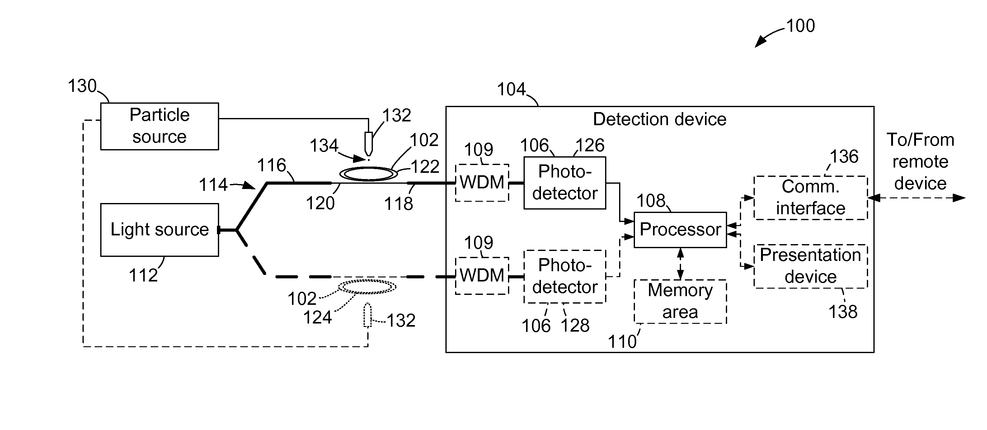
[0038]Embodiments described herein facilitate detecting the presence and the polarizability, which is related to the size, the composition, and / or the refractive index, of one or more objects on the surface of a whispering gallery mode (WGM) resonator. Accordingly, such embodiments enable the creation of a portable, inexpensive, and high-resolution device capable of real-time and in-situ detection of particles surpassing current detection limits.

[0039]The embodiments described herein further facilitate detecting and counting nanoparticle with a tapered optical fiber having a sub-wavelength diameter. The individual particles are detected as they enter an evanescent field of the tapered optical fiber. Further, the individual particles may be detected without labeling (e.g., fluorescent dyes). Unlike at least some known particle detection systems, the particle detection systems and methods described herein do not require tunable lasers, bulky optical components, and / or lengthy signal p...


PUM


Abstract

A particle detection system is provided. The particle detection system includes at least one tapered optical fiber, a light source configured to transmit light through the at least one tapered optical fiber, a photodetector configured to measure a characteristic of the light being transmitted through the at least one optical fiber, and a computing device coupled to the photodetector and configured to determine whether a nanoparticle is present within an evanescent field of the at least one tapered optical fiber based on the measured light characteristic.

Description

CROSS REFERENCE TO RELATED APPLICATIONS[0001]This application is a continuation-in-part of U.S. patent application Ser. No. 12 / 966,785, filed 13 Dec. 2010, which claims the benefit of U.S. Provisional Patent Application No. 61 / 285,869, filed 11 Dec. 2009, both of which are hereby incorporated by reference in their entirety.STATEMENT REGARDING FEDERALLY SPONSORED RESEARCH & DEVELOPMENT[0002]This invention was made with government support under NSF-DMR-0907467 and NSF-ECCS-0954941 awarded by The National Science Foundation. The government may have certain rights in the invention.BACKGROUND[0003]With recent progress in nanotechnology, nanoparticles of different materials and sizes have been synthesized and engineered as key components in various applications ranging from solar cell technology to the detection of biomolecules. Meanwhile, nanoparticles generated by vehicles and industry have become recognized as potential threats to health and environment. Microscopy and spectroscopy tec...

Claims


Application Information

Patent Timeline
IPC IPC(8): G01N15/02G01N21/59
CPCG01N21/7746B82Y35/00Y10S977/88
Inventor ZHU, JIANGANGOZDEMIR, SAHIN KAYAYANG, LAN
Owner WASHINGTON UNIV IN SAINT LOUIS
Learn More