
Gas analyzing system

a gas analysis and gas technology, applied in the field of gas analysis systems, can solve the problems of reducing the accuracy and reliability of an analysis, affecting the accuracy of analysis, and denatured gas itself, and achieve the effects of high accuracy, high accuracy of calibration, and high reliability of analysis results

Active Publication Date: 2012-10-18
HORIBA LTD
View PDF4 Cites 12 Cited by
  • Summary
  • Abstract
  • Description
  • Claims
  • Application Information

AI Technical Summary

Benefits of technology

[0012]As described, according to the present invention, highly accurate calibration can be performed, so that a highly reliable analysis result can be obtained, and even in the case where concentration of a measuring target component in sample gas is low, a highly accurate analysis result can be obtained.

Problems solved by technology

Such zero gas or span gas is generally filled in a high-pressure cylinder, and supplied to the gas analyzing system through a supply line for each gas; however, if calibration has not been performed for a long time, concentration of the span gas remaining in various types of pipes constituting a span gas supply line may be varied, or the gas itself may be denatured or deteriorated.
Even if the calibration is performed with use of the span gas deteriorated as described, appropriate calibration is not performed to cause reductions in accuracy and reliability of an analysis result.

Method used


Image

  • Gas analyzing system
  • Gas analyzing system
  • Gas analyzing system

Examples


Embodiment Construction

[0016]In the following, one embodiment of the present invention is described with reference to the drawings.

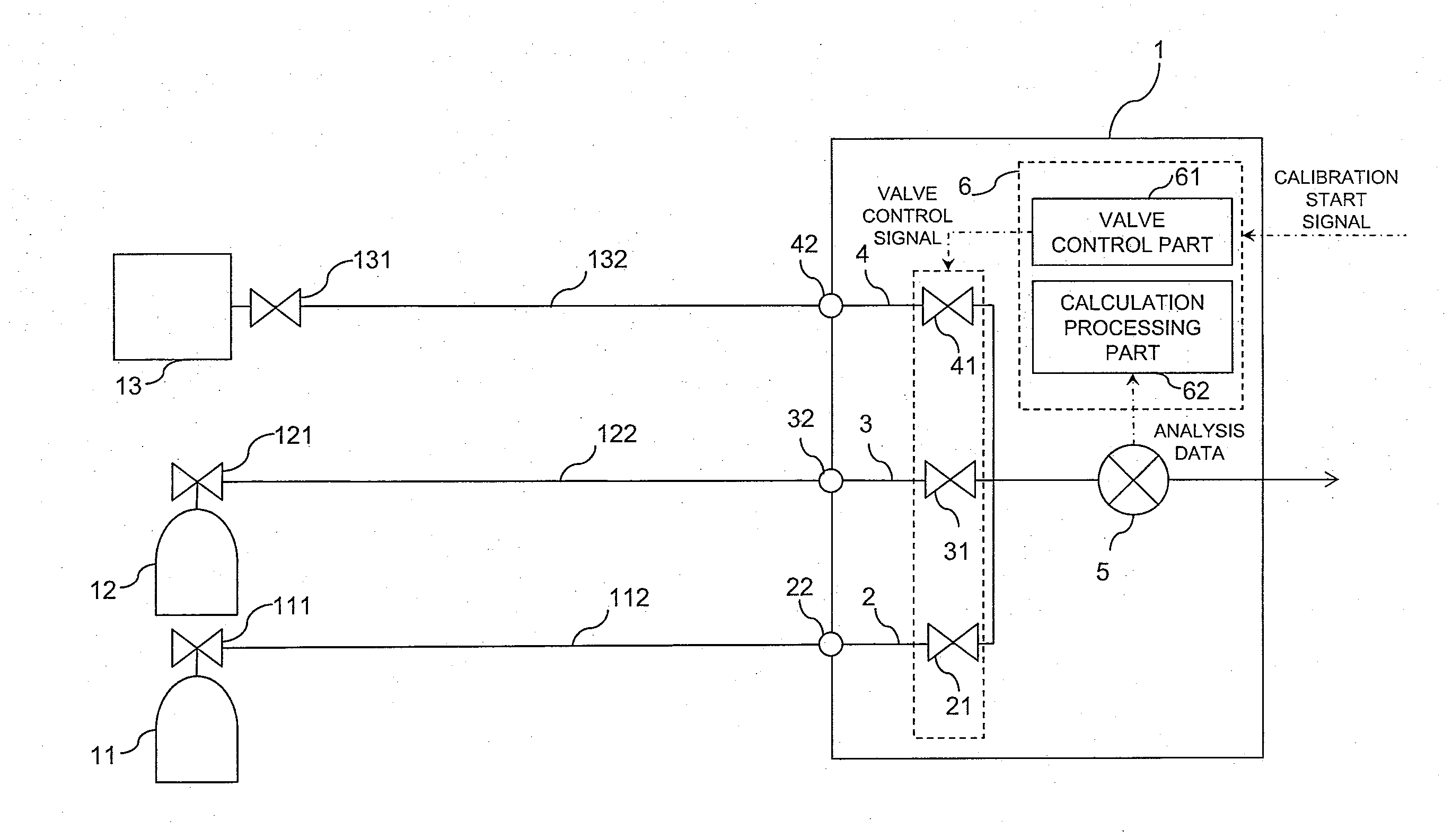
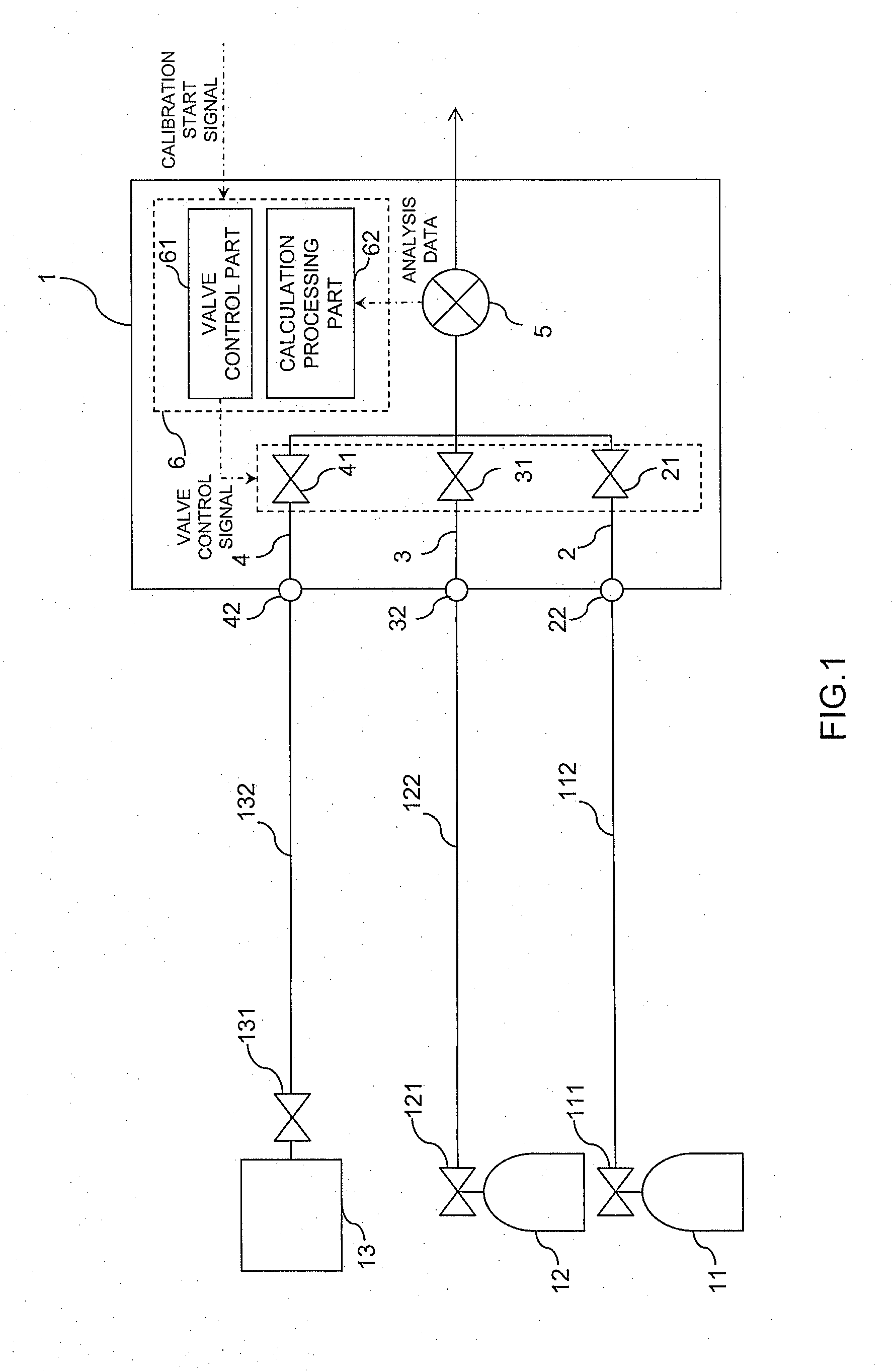
[0017]A gas analyzing system 1 according to the present embodiment is, as illustrated in FIG. 1, provided with: a zero gas flow path 2; a span gas flow path 3, a sample gas flow path 4, a gas analyzer 5 that is provided on a downstream side of these flow paths and analyzes a measuring target component in sample gas; and an information processor 6.

[0018]The zero gas flow path 2, span gas flow path 3, and sample gas flow path 4 are respectively provided with open-close valves 21, 31, and 41, and inlet ports 22, 32, and 42 of the respective flow paths are connected to corresponding gas supply lines 112, 122, and 132. Also, the respective flow paths 2, 3, and 4 are connected to corresponding gas supply sources 11, 12, and 13 through the supply lines 112, 122, and 132.

[0019]Each of the gas supply lines 112, 122, and 132 is formed of a resin pipe such as a fluorine resin pipe or nyl...


PUM


Abstract

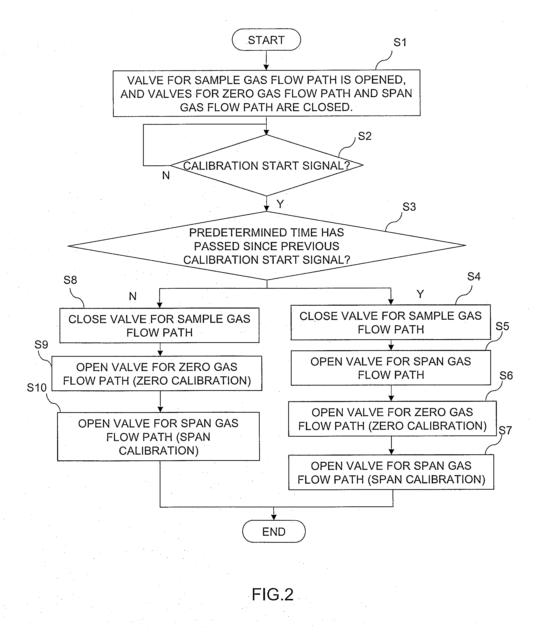
A gas analyzing system that can perform calibration without being influenced by the deterioration of span gas in a span gas supply line. An open-close device control part that receives a calibration start signal issuing an instruction to start zero calibration and span calibration, and controls an open-close device for a span gas flow path. An open-close device for a zero gas flow path, wherein if the open-close device control part receives a new calibration start signal after a predetermined time has passed since previous calibration was performed, before the span calibration is started, for a predetermined time, the open-close device control part controls the open-close device for the span gas flow path so as to open the open-close device for the span gas flow path, and thereby purges span gas that remains in the span gas flow path.

Description

TECHNICAL FIELD[0001]The present invention relates to a gas analyzing system that achieves superior measurement accuracy.BACKGROUND ART[0002]In the past, in the case of measuring concentrations of various types of components in exhaust gas, or various types of components generated or processed in various types of processes, various types of gas analyzers have been used, such as a non-dispersive infrared gas analyzer (NDIR), non-dispersive ultraviolet gas analyzer (NDUV), magnetic oxygen analyzer, chemiluminescence detecting type nitrogen oxide analyzer (CLD type NOx analyzer), and hydrogen flame ionization detector (FID) (Patent literature 1). In a gas analyzing system provided with such a gas analyzer, before measurement, calibration using zero gas and span gas is performed. In such calibration, first, the zero gas is flowed through the gas analyzer to perform zero calibration, and then the span gas is flowed through the gas analyzer to perform span calibration.[0003]Such zero gas ...

Claims


Application Information

Patent Timeline
IPC IPC(8): G01N33/00G01D18/00
CPCG01N21/274G01N33/0004G01N21/3504G01N21/766G01N21/61G01N21/72G01N33/006G01N33/0006
Inventor MIYAI, MASARUNISHIKAWA, MASAHIRO
Owner HORIBA LTD
Learn More