
Pipette Tip Stacking Tray

a technology of stacking tray and pipette tip, which is applied in the field of stacking tray with pipette tip, can solve the problems of affecting the organization of stacking tray, defeating the organizational purposes and convenience of stacking tray, and affecting the practicality of stacking tray containing filter pipette tip, and conventional stacking arrangements that are not practical

Active Publication Date: 2012-10-11
MOLECULAR BIOPROD
View PDF4 Cites 47 Cited by
  • Summary
  • Abstract
  • Description
  • Claims
  • Application Information

AI Technical Summary

Benefits of technology

[0005]The present invention overcomes the foregoing problems and other shortcomings, drawbacks, and challenges of stacking conventional pipette tip trays for use with a storage container or rack. While the invention will be described in connection with cert

Problems solved by technology

However, the stacking of multiple trays containing pipette tips is not straightforward because the overall length of each pipette tip is often greater than the thickness of the tray.
This defeats the organizational purposes and convenience of stackable trays.
While in some applications this may not present a problem, the known conventional stacking arrangements are not practical for stacking trays containing filter pipette tips.
Because known alternative arrangements for stacking pipette tip trays have not provided satisfactory solutions for filter pipette tips, i.e., stacking is neither efficient with respect to storage capability nor conducive to the laboratory environment where technicians often wear gloves with diminished dexterity or handling by laboratory robotics, there remains a need for a pipette tip tray that is capable of supporting pipette tips, particularly filter pipette tips, and that is stackable in a simple but efficient manner for use with a pipette tip rack.

Method used


Image

  • Pipette Tip Stacking Tray
  • Pipette Tip Stacking Tray
  • Pipette Tip Stacking Tray

Examples


Embodiment Construction

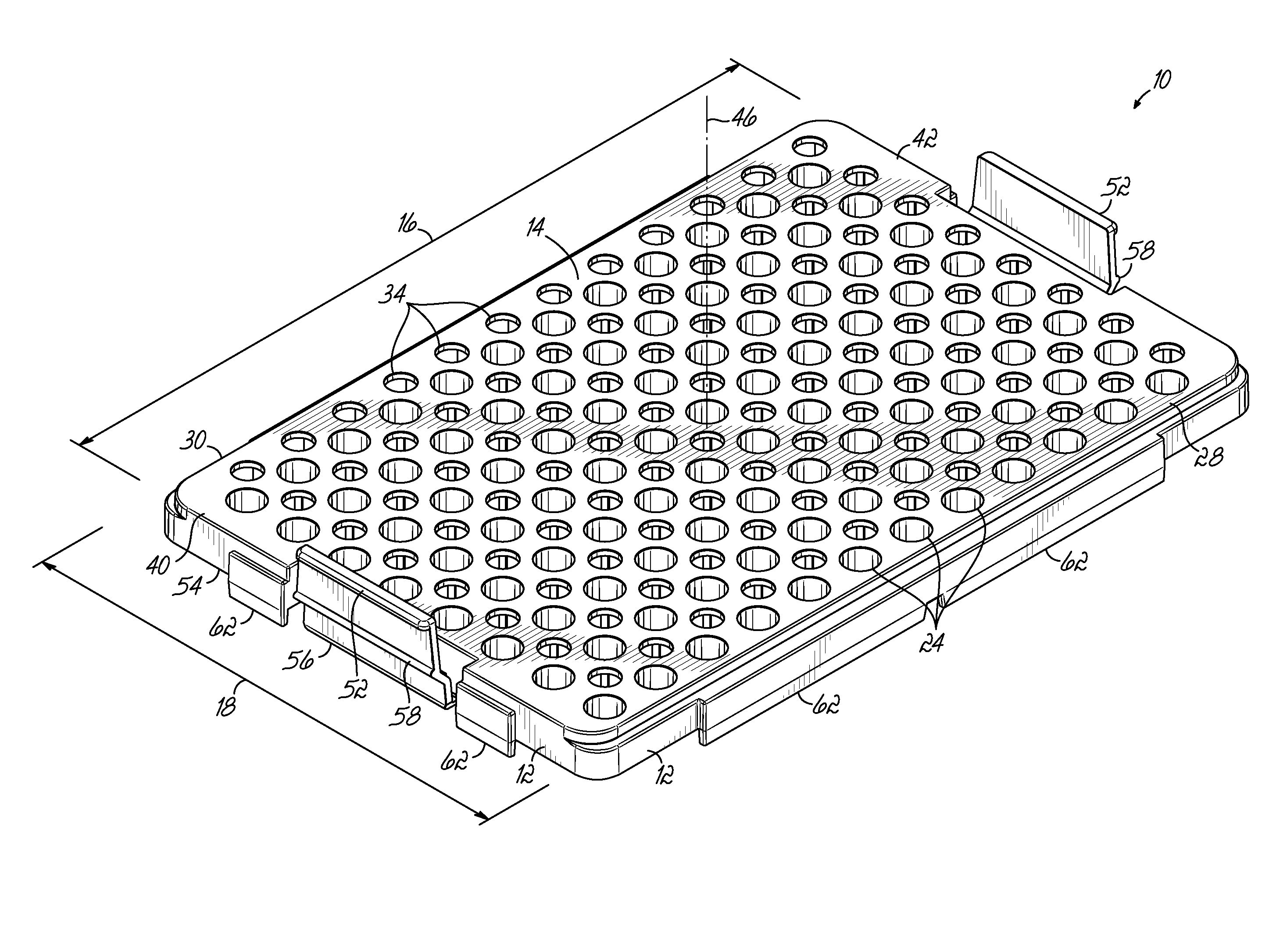
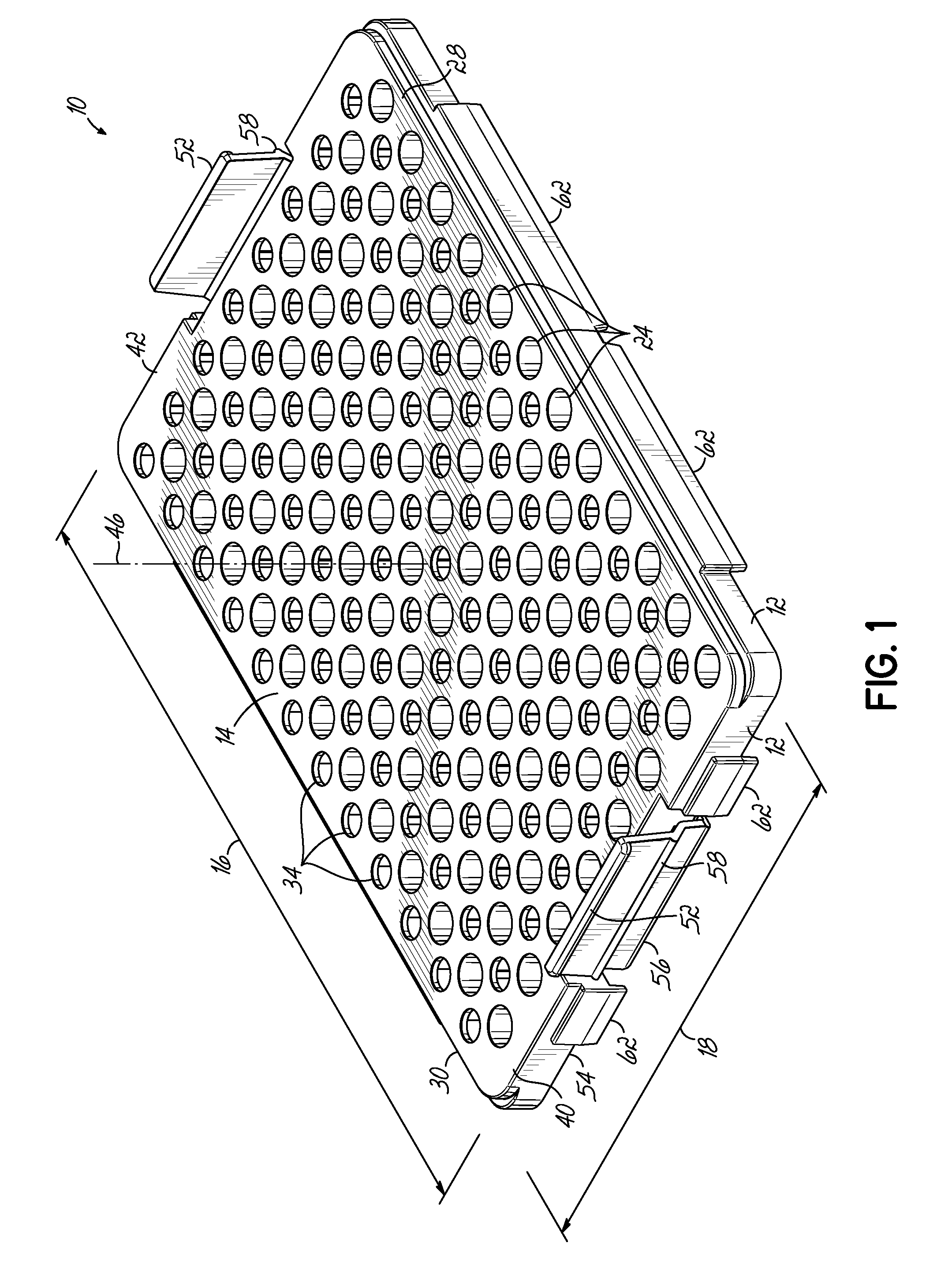
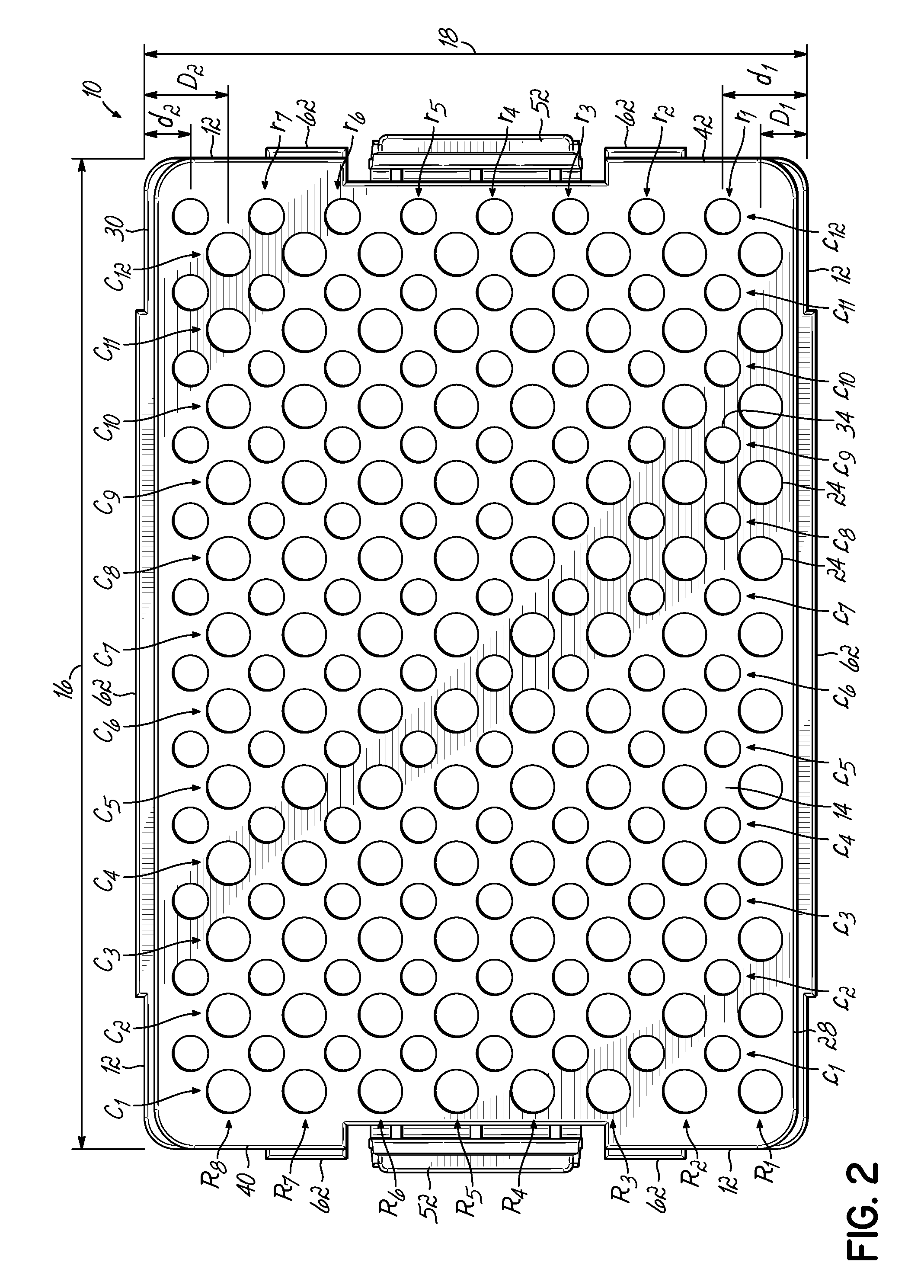
[0021]Turning now to the figures, and particularly to FIGS. 1-3, a first embodiment of a pipette tip tray (“tray”10) is shown and described in detail. The tray 10 includes opposing end-walls and opposing sidewalls 12 and a planar deck 14 having a longitudinal dimension (arrow 16) and a lateral dimension (arrow 18). The deck 14 includes a first set of apertures having a first size or shape that is configured to receive the shaft 20 (FIG. 4) of a pipette tip 22 (FIG. 4) (“shaft apertures”24). The pipette tips 22 may be of any desired size, but are particularly illustrated in FIGS. 1-7 for use with medium sized pipette tips, e.g., 20 μL to 300 μL sized pipette tips.

[0022]The shaft apertures 24 are arranged into a plurality of rows along the longitudinal dimension and such that the outer row of shaft apertures 24 that is adjacent to a first longitudinal side edge 28 of the deck 14 is positioned closer to the first longitudinal side edge 28 than the outer row of shaft apertures 24 adjace...


PUM


Abstract

A stackable pipette tip tray is described. The pipette tip tray includes a deck having first and second opposing longitudinal side edges. A plurality of shaft apertures is arranged into a plurality of longitudinal rows on the deck. Each of the shaft apertures has a first size or shape configured to receive a shaft of a pipette tip. The deck also includes a plurality of tip apertures that is also arranged into a plurality of longitudinal rows such that at least one of the longitudinal rows of tip apertures is located between an adjacent pair of longitudinal rows of shaft apertures. Each of the plurality of tip apertures has a second size or shape, different from the first size or shape, and is configured to receive a distal tip end of a pipette tip when one tray of pipette tips is stacked above another tray of pipette tips. The plurality of longitudinal rows of shaft apertures is further arranged such that an outer one of the plurality of longitudinal row of shaft apertures adjacent the first side edge of the deck is positioned closer to the first side edge than an outer one of the plurality of longitudinal row of shaft apertures adjacent the second side edge of the deck is positioned relative to the second side edge.

Description

FIELD OF THE INVENTION[0001]The present invention relates generally to pipette tip trays and, more particularly, to stackable pipette tip trays for use with pipette tips, including filter pipette tips.BACKGROUND OF THE INVENTION[0002]Disposable pipette tips are often packaged within trays that function to support and organize the pipette tips and to aid in the placement of one or more pipette tips onto a pipetter having one or more channels. These trays may be housed within a container or rack that is convenient for bench-top applications.[0003]Often, the trays are either refillable, i.e., pipette tips may be reloaded into an empty tray, which may or may not be sterilized between uses, or disposable and replaceable with a filled tray. In either situation, multiple trays may be packaged together in a stack for storage convenience and for efficient reloading of a rack with a new filled tray of pipette tips after the previous tray is emptied of its pipette tips during use. However, the...

Claims


Application Information

Patent Timeline
IPC IPC(8): B01L9/00B65G57/03
CPCB01L3/0275B01L2200/025B01L9/543
Inventor WILLIAMS, ERICREDDY, HARI
Owner MOLECULAR BIOPROD
Learn More