Method and an apparatus in a ventilation system

Inactive Publication Date: 2012-10-11
R VENT GRP BV
View PDF9 Cites 3 Cited by
  • Summary
  • Abstract
  • Description
  • Claims
  • Application Information

AI Technical Summary

Benefits of technology

[0008]It is desirable to formulate the method intimated by way of introduction so that a humidification of the supply air may take place utilising the thermal content of the exhaust air for vaporisation

Problems solved by technology

A heat exchanger of this type cannot be regulated as regards the humidification of the supply air, for which reason major problems may occur in certain weather conditions.
Further, the transfer of humidity in a heat exchanger of this type is incomplete as the major part of the condensation takes place in the coldest part of the heat exchanger where the air on the opposite side of the heat exchanger wall due to the low temperature has a bad ability to absorb humidity.

Method used


Image

  • Method and an apparatus in a ventilation system
  • Method and an apparatus in a ventilation system
  • Method and an apparatus in a ventilation system

Examples


Embodiment Construction

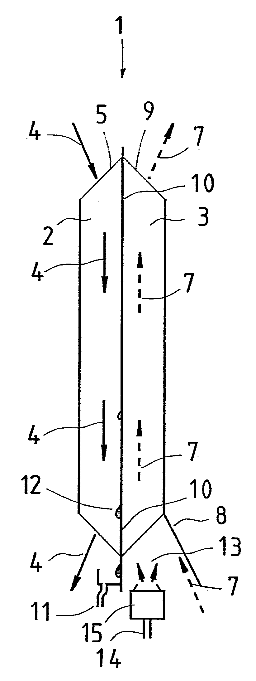
[0016]In FIG. 1, reference numeral 1 relates to a heat exchanger which operates in counter flow and which has an exhaust air side 2 and a supply air side 3. The exhaust air side may also be entitled the warm side of the heat exchanger and the supply air side be entitled its cold side. The exhaust air 4 flows in accordance with the arrows from above and downwards in the Figure from an exhaust air inlet 5 to an exhaust air outlet 6.

[0017]Correspondingly, the supply air 7 flows according to the broken line arrows in a direction from beneath from a supply air inlet 8 in an upward direction to a supply air outlet 9. The partition 10 between the exhaust air side 2 and the supply air side 3 consists of or comprises a thermally conductive material, which is gas-tight and impermeable to water, such as copper, aluminium or certain plastics qualities. The wall thickness of the partition is so slight that the wall may be designated a foil.

[0018]If it is assumed that the incoming supply air 7 at...


PUM


Abstract

A method for recovering heat and humidity in a ventilation system includes cooling warm and humid exhaust air at a condensation surface in a heat exchanger and collecting the condensate as formed, heating dry and cold supply air at the opposite side of the condensation surface and atomizing the condensate and supplying the atomized condensate to the supply air at the supply air inlet of the heat exchanger. The atomizing is generated b a piezoelectric atomizer. A device for recovering heat and humidity in a heat exchanger in a ventilation system includes a condensation surface at the exhaust air side of the heat exchanger and a collection device for condensate. At the inlet of the supply air side of the heat exchanger there is provided a piezoelectric atomizer that is fed with the condensate for supplying atomized condensate to the inlet.

Description

BACKGROUND AND SUMMARY[0001]The present invention relates to a method, in a ventilation system, of transferring heat and humidity from departing exhaust air to incoming supply air, and comprises the steps that heat is extracted from the exhaust air in an exhaust air side of a heat exchanger, that the extracted heat is at least partly transferred to the supply air in a supply air side of a heat exchanger, and that humidity carried by the exhaust air is bonded in the exhaust air side and at least partly transferred to the supply air.[0002]The present invention also relates to an apparatus, in a ventilation system, for transferring heat and humidity from departing exhaust air to incoming supply air, and comprises a heat exchanger with a supply air side and an exhaust air side, and means for bonding humidity and at least partly transferring this humidity to the supply air.[0003]In the ventilation of dwellings, use is nowadays almost exclusively made of balanced ventilation where, with t...

Claims


Application Information

Patent Timeline
IPC IPC(8): F28D15/00F28F27/00
CPCF24F6/00F24F3/147F24F13/222F24F6/12F24F12/006Y02B30/56F24F6/02
Inventor WALLIN, PETER
Owner R VENT GRP BV
Why Eureka
Try Eureka