
Modular Mounting Apparatus

Inactive Publication Date: 2012-10-11
HENDRICKSON REYNOLD +2
View PDF8 Cites 24 Cited by
  • Summary
  • Abstract
  • Description
  • Claims
  • Application Information

AI Technical Summary

Benefits of technology

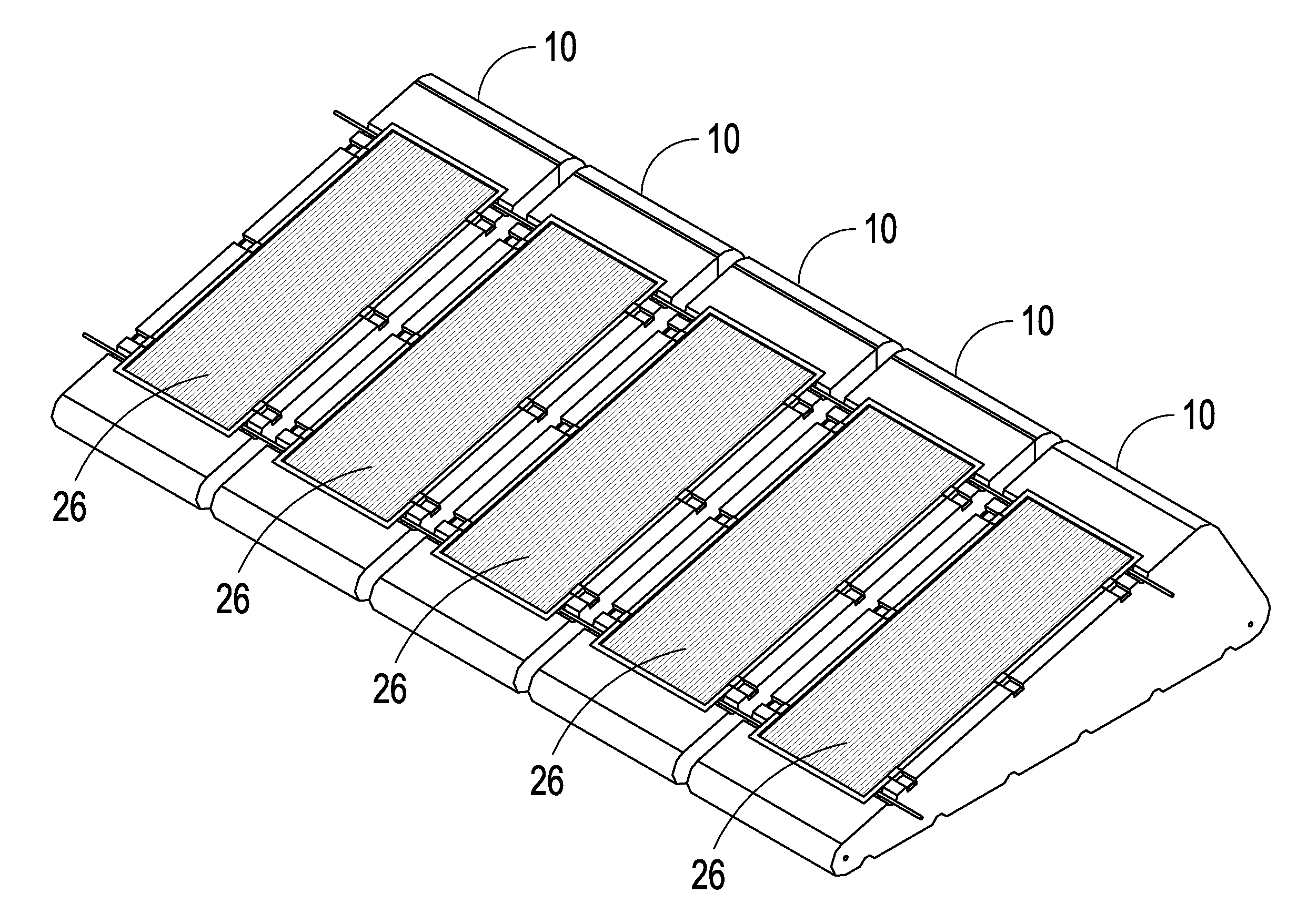
[0008]A modular mounting apparatus for solar panels is disclosed. The mounting apparatus has a number of embodiments designed to reduce or eliminate the need for roof-top anchors. The mounting apparatus has a cavity that can be loaded with a heavy substance, to prevent the mounting apparatus from moving. The mounting apparatus also includes a system to mate several mounts together, creating a larger, more inert mass. The mounting apparatus comes with a tethering system to reduce the number of roof-top anchors.

Problems solved by technology

Traditionally, building owners were reluctant to fasten large items to their roof, for fear that the equipment would be damaged by the elements.
One drawback of current technology is that, when mounted to a flat top roof, often found with commercial buildings, it requires the use of many drill holes.
Adding holes to sealed rooftops provokes leakage by creating paths for water to find its way inside the building, potentially damaging the structure and the interior of the building.
The more holes that are added to anchor a component to a roof, the more potential for leak paths and water entry into the building.
Often, current mounting apparatus are manufactured of steel, aluminum, or like metal, that are heavy, large and bulky to transport and install.
They may also add additional unnecessary weight to any roof.
These mounting systems may also be quite costly to manufacture, transport and install.

Method used


Image

  • Modular Mounting Apparatus
  • Modular Mounting Apparatus
  • Modular Mounting Apparatus

Examples


Embodiment Construction

[0031]The detailed description is intended to illustrate the present invention, without, in any way, limiting its scope. The drawings are not scale models, and the drawings do not show all the potential embodiments of the present invention. The drawings represent the preferred embodiment, and important alternative embodiments of the present invention, known to the inventors.

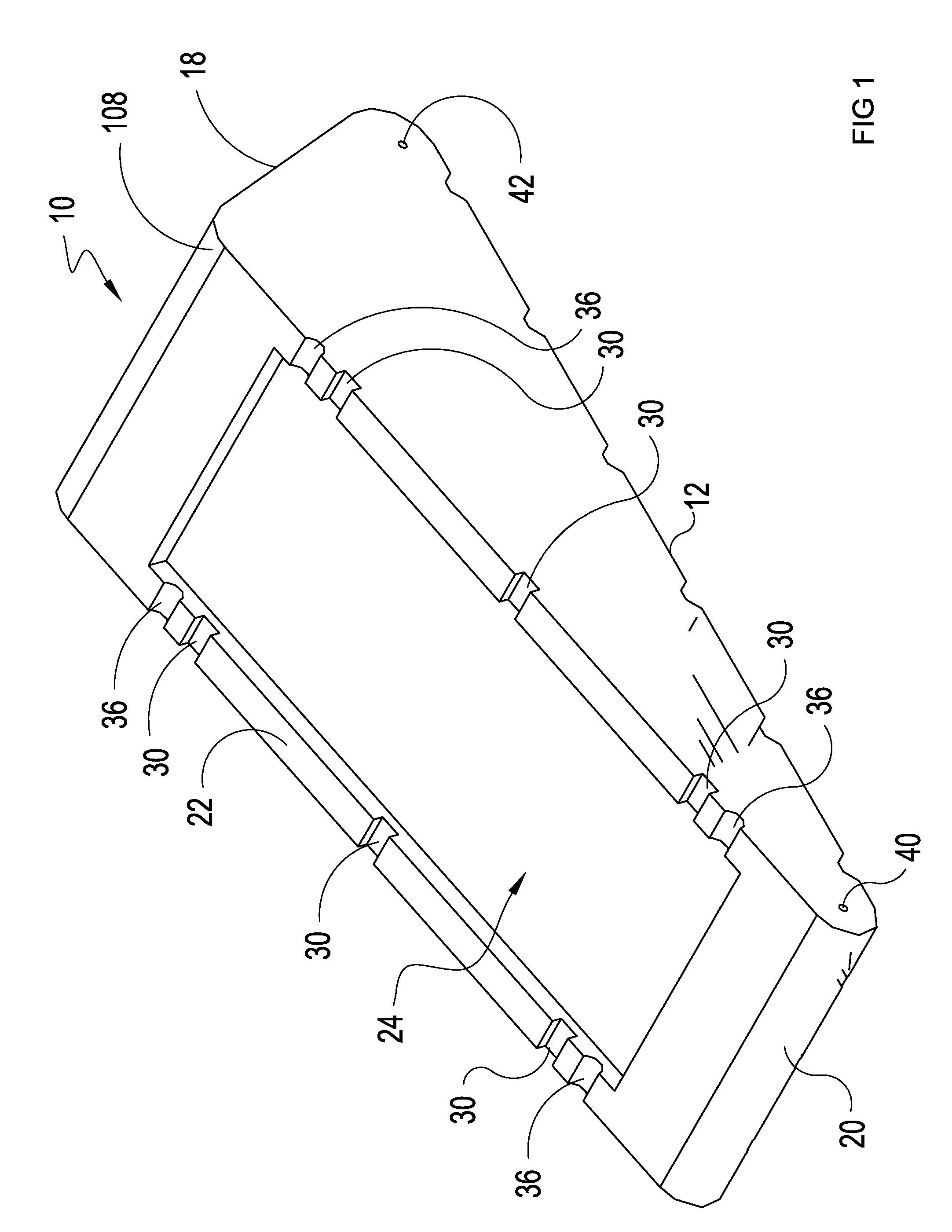
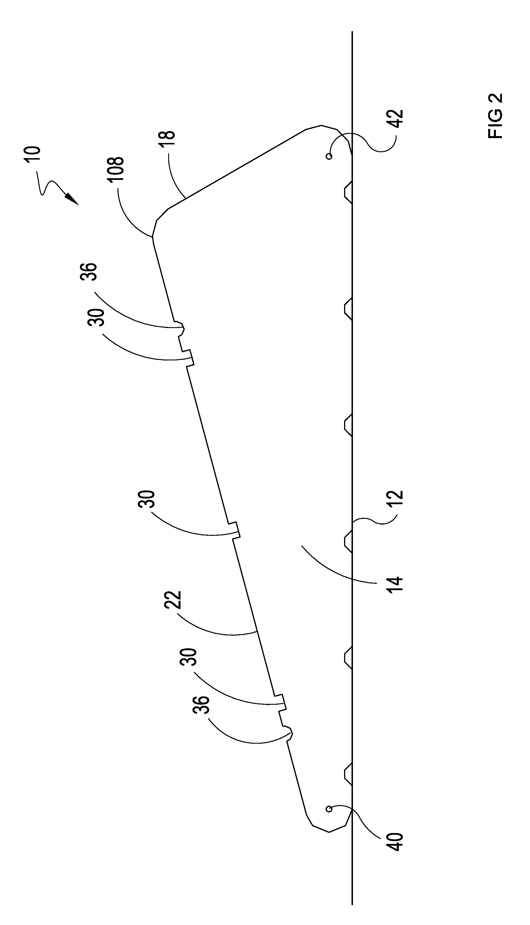
[0032]A mounting apparatus 10 is illustrated in FIGS. 1-4. The mounting apparatus 10 is in the general shape of a wedge and is comprised of a base surface 12, a pair of side walls 14 and 16, a rear wall 18, a front wall 20 and a top surface 22. Side walls 14 and 16 extend upward and generally perpendicular from the base surface 12. Side wall 14 and 16 are also generally parallel to one another. Rear wall 18 extends upward from base surface12 and at an angle that is generally less than 90 degrees. Rear wall 18 also intersects side wall 14 and 16. Front wall 20 extends upward from base surface as well and intersect...


PUM


Abstract

A mounting apparatus, primarily for solar panels and other renewable energy panels. The mounting apparatus has a base, sides, a front, a back, and a top. It is generally wedge-shaped. It has a depression designed to fit photovoltaic and solar thermal panels. It has a number of mounting mechanisms, including ballast, tethers, and fasteners, designed to minimize the number of roof-top holes needed to anchor a system.

Description

CLAIM OF PRIORITY[0001]The applicants claims priority under 35 USC 119, et. seq., to a prior filed provisional utility patent application No. 61 / 474,263, filed Apr. 11, 2011; entitled, “Modular Mounting Apparatus;” by named inventors Rajul L. Patel, Reynold Hendrickson, and Jon Karpovich.FIELD OF INVENTION[0002]This invention relates to the field of mounting apparatus. Specifically, this invention relates to the mounting hardware and methods for renewable energy panels, satellites, and other roof mounted equipment.BACKGROUND OF INVENTION[0003]Mounting apparatus have been developed over the years to anchor items such as signs, solar panels, satellite dishes, HVAC units and the like to buildings and the ground. Many of these apparatus are used on the roof. For many items the roof is the ideal mounting location. For instance, the roof is an ideal mounting location for a solar panel because it is not obstructed from the sun. Additionally, the roof is the ideal mounting place for billboa...

Claims


Application Information

Patent Timeline
IPC IPC(8): E04D13/18E04B1/38
CPCH01L35/30Y02B10/20F24J2/0477F24J2/30Y02E10/47F24J2/5239F24J2002/467F24J2002/5292Y02E10/44F24J2/5237F24S25/16F24S2025/6007F24S25/11F24S10/30F24S10/20F24S2025/02H10N10/13
Inventor HENDRICKSON, REYNOLDPATEL, RAJULKARPOVICH, JON
Owner HENDRICKSON REYNOLD
Learn More