Temperature-sensitive pellet type thermal fuse

a technology of thermal fuse and pellet type, which is applied in the manufacture of emergency protective devices, wave amplitude devices, electric devices, etc., can solve the problems of defective cut-off of power source circuit, delay in operation of -sensitive pellet type thermal fuse 50/b>, and increase the complexity of the electric product structure, so as to ensure the versatility of the arrangement of the fuse and enhance the versatility of the arrangement. , the effect of high heat response speed

Inactive Publication Date: 2012-10-11
THE HOSHO CORP
View PDF15 Cites 5 Cited by
  • Summary
  • Abstract
  • Description
  • Claims
  • Application Information

AI Technical Summary

Benefits of technology

[0065]According to the invention called for in claim 1, the elongated case has the planar portion which is brought into face contact with the planar portion of the temperature control target object. Accordingly, when the elongated case is mounted on the temperature control target object having the planar portion, different from the conventional case where the elongated case and the temperature control target object are brought into contact with each other by line contact, a large contact surface is obtained thus allowing the fuse to ensure a high heat response speed by high-speed heat conduction.
[0066]Further, according to the inventions called for in claims 2 and 3, the elongated case is formed into the regular multi-sided cylinder or the regular four-sided cylinder. Accordingly, in addition to the advantage acquired by the invention described in claim 1, when an arbitrary side surface portion of the elongated case is mounted on the planar portion of the temperature control target object, the elongated case has a plurality of planar portions which are brought into contact with the temperature control target object and hence, even when the temperature control target object has a plurality of planar portions, the elongated case is effectively brought into face contact with the temperature control target object whereby it is possible to ensure the versatility of the arrangement of the fuse.
[0067]Further, any one of surfaces of the elongated case can be arranged to be brought into contact with the planar portion of the temperature control target object and hence, the planar portion of the elongated case for contact is not limited thus further enhancing the versatility of the arrangement.
[0068]Further, according to the invention called for in claim 4, on the other longitudinal end portion of the elongated case, the bushing fixing stepped portion is formed in an over a predetermined length. Accordingly, it is possible to position the second lead line and a bushing arranged on a peripheral portion of the second lead line on the other longitudinal end portion of the elongated case with high accuracy, and it is also possible to fix the second lead line and the bushing in a more stable manner.
[0069]Further, according to the invention called for in claim 5, the wall thickness of the planar portion of the elongated case which is brought into contact with the temperature control target object is set to 0.4 mm or less, and the wall thickness of the bushing fixing stepped portion is set to 0.2 mm. Accordingly, the wall thickness of the portion of the elongated case which is brought into contact with the planar portion of the temperature control target object is small so that it is also possible to shorten a heat response time in addition to the advantage acquired by the invention described in claim 1.
[0070]Further, according to the invention called for in claim 6, the surface roughness of the planar portion of the elongated case is set such that the difference between the concave portion and the convex portion of the uneveness is set to 6.3 μm or less. Accordingly, it is possible to bring the planar portion of the elongated case into close contact with the planar portion of the temperature control target object and hence, the elongated case can ensure a large heat receiving area whereby it is possible to further shorten the heat response time due to a large heat conduction effect.

Problems solved by technology

An electric product of nowadays is constituted of various kinds of parts and, particularly recently, the structure of the electric product is becoming more complicated.
Due to a storage of heat in the temperature control target object, when a temperature of a part is excessively elevated, an erroneous operation of the part is induced resulting in the occurrence of ignition.
Accordingly, there has been a drawback that a heat response speed from a point of time that the temperature of the temperature control target object 64 reaches a predetermined temperature to a point of time that the temperature-sensitive pellet type thermal fuse 50 is operated is delayed.
Accordingly, the above-mentioned temperature-sensitive pellet type thermal fuse has a drawback that the fuse causes a defective cut-off of a power source circuit in addition to delaying of a heat response speed.
Accordingly, it is difficult for the conventional temperature-sensitive pellet type thermal fuse 50 provided with the cylindrical case to ensure the sufficient operational reliability.
Further, due to tolerance in machining accuracy, it is difficult to maintain a heat response time at a fixed value for every product.
Further, it is also impossible to completely prevent a defective cut-off thus giving rise to a drawback that it is difficult for the temperature-sensitive pellet type thermal fuse 70 to ensure the high operational reliability.Patent document 1: JP-A-11-306939

Method used


Image

  • Temperature-sensitive pellet type thermal fuse
  • Temperature-sensitive pellet type thermal fuse
  • Temperature-sensitive pellet type thermal fuse

Examples


embodiment 1

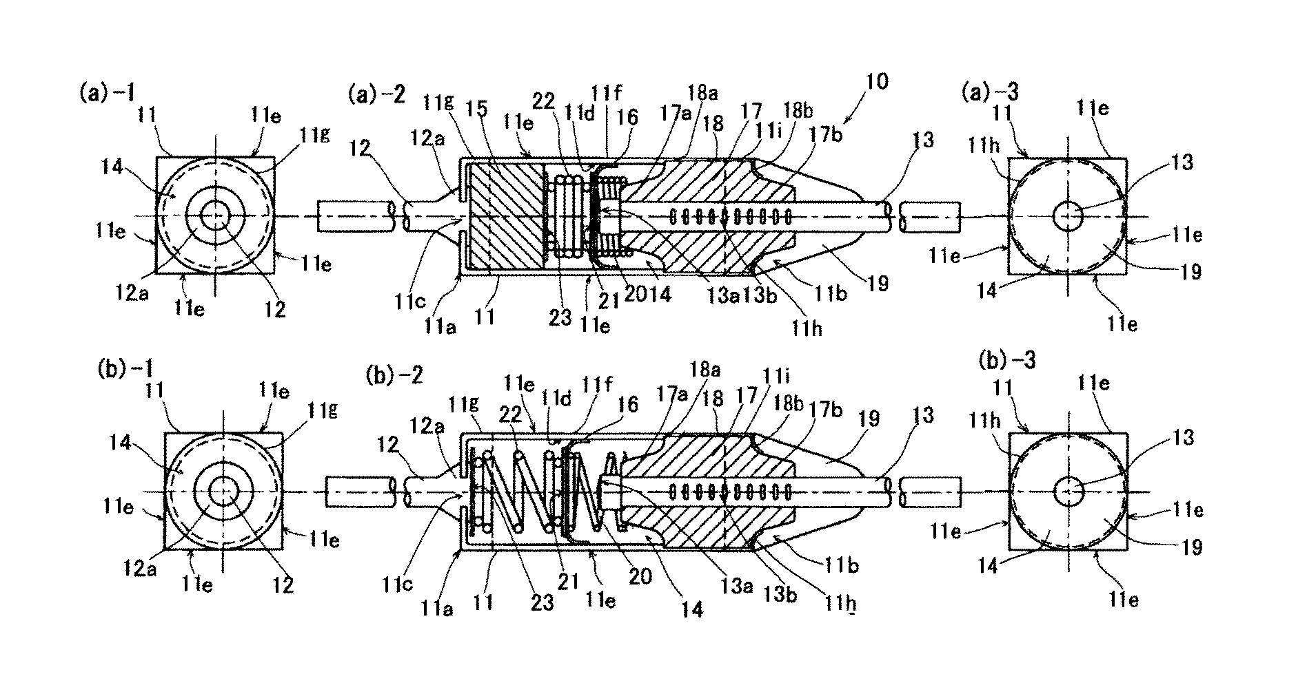
[0098]Hereinafter, the constitution of this embodiment is explained in detail in conjunction with drawings.

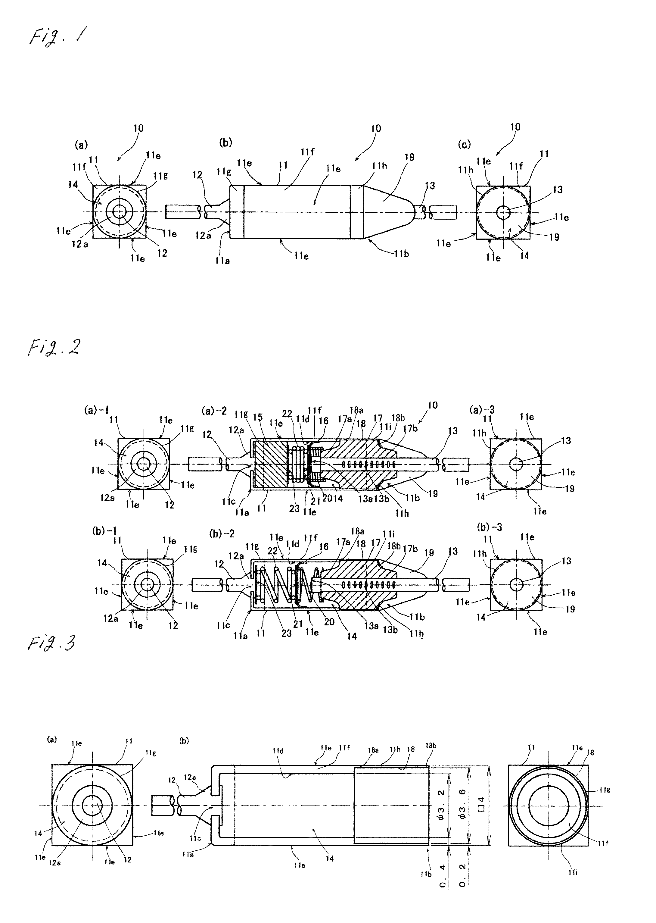
[0099]FIG. 1 shows a temperature-sensitive pellet type thermal fuse 10 according to this embodiment, wherein FIG. 1(a) is a front view of the temperature-sensitive pellet type thermal fuse 10, FIG. 1(b) is a whole side view of the temperature-sensitive pellet type thermal fuse 10, and FIG. 1(c) is a rear view of the temperature-sensitive pellet type thermal fuse 10.

[0100]As shown in FIG. 1(a) to FIG. 1(c), the temperature-sensitive pellet type thermal fuse 10 according to this embodiment includes a four-sided cylindrical case 11 which is formed into a substantially regular four-sided cylinder as a whole, wherein the case 11 has a longitudinal length of 8 mm. The four-sided cylindrical case 11 is constituted of a case body portion 11f, the above-mentioned case body portion 11f, and cylindrical projecting portions 11g, 11h which are formed on both longitudinal end portions of the...

embodiment 2

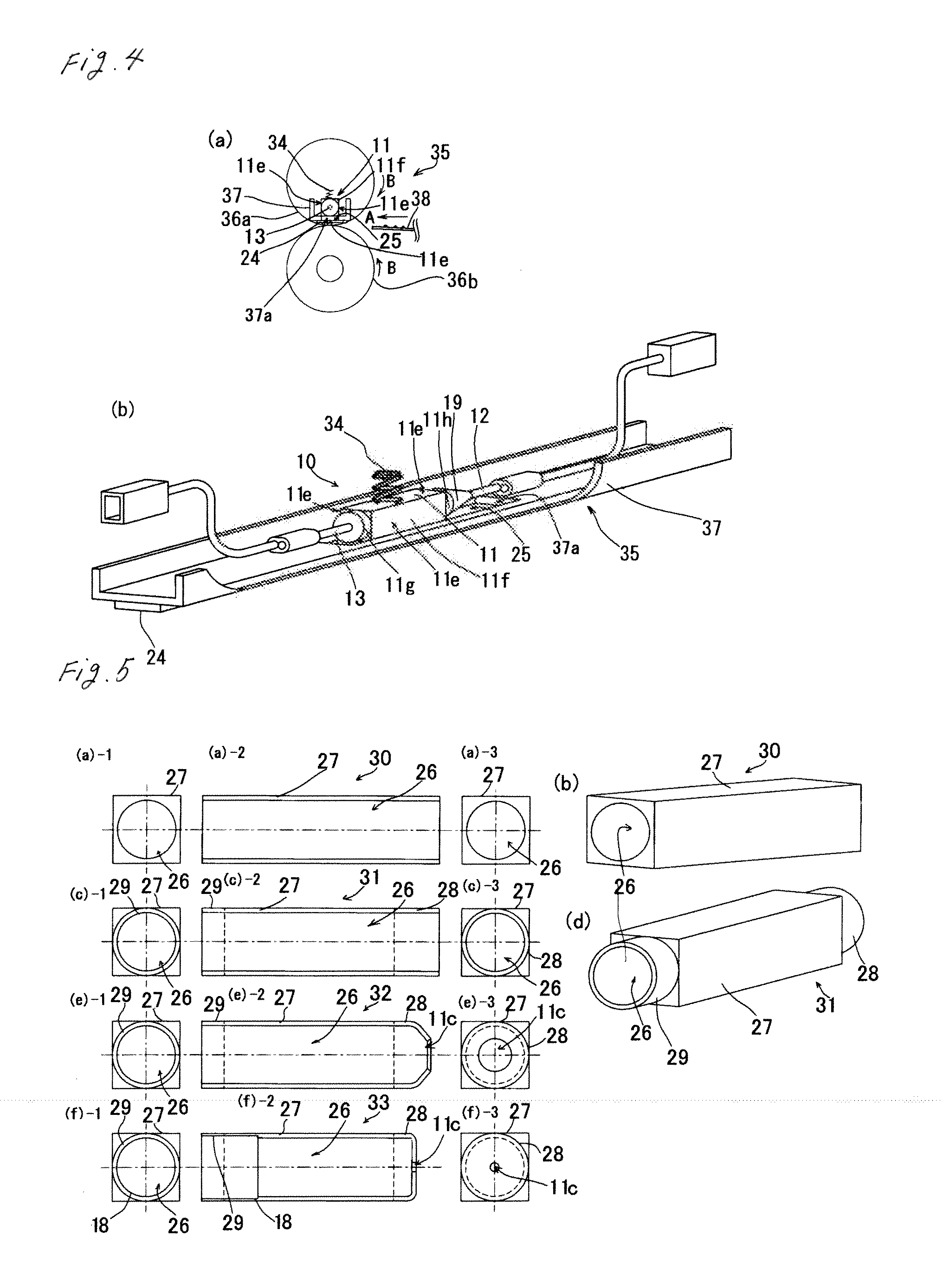
[0164]Further, FIG. 6 shows another example of manufacturing steps of the four-sided cylindrical case of the temperature-sensitive pellet type thermal fuse 10 according to this embodiment, wherein FIG. 6(a)-1 is a front view of the four-sided cylindrical case base member 27 in step 40, FIG. 6(a)-2 is a side view of the four-sided cylindrical case base member 27, FIG. 6(a)-3 is a rear view of the four-sided cylindrical case base member 27, FIG. 6(b) is a perspective view of the four-sided cylindrical case base member 27 in the same step 40, FIG. 6(c)-1 is a front view of the four-sided cylindrical case base member 27 in step 41, FIG. 6(c)-2 is a longitudinal cross-sectional view of the four-sided cylindrical case base member 27, FIG. 6(c)-3 is a rear view of the four-sided cylindrical case base member 27 in step 41, and FIG. 6(d) is a perspective view of the four-sided cylindrical case base member 27 in step 41.

[0165]The four-sided cylindrical case 11 of the temperature-sensitive pel...


PUM

PropertyMeasurementUnit
thicknessaaaaaaaaaa
thicknessaaaaaaaaaa
surface roughnessaaaaaaaaaa

Abstract

The present invention provides a temperature-sensitive pellet type thermal fuse, a manufacturing method of the temperature-sensitive pellet type thermal fuse and a mounting method of the temperature-sensitive pellet type thermal fuse which, when the fuse is mounted on a temperature control target object having a planar portion, can ensure a high heat response speed, can decrease the difference in a heat response time for every product, can ensure high operational reliability, reduces the number of parts, and can reduce a manufacturing cost. A temperature-sensitive pellet type thermal fuse includes: an elongated case which has a hollow portion in the inside thereof; a first lead line which is arranged on one longitudinal end portion side of the elongated case along the longitudinal direction; a second lead line which is arranged on the other longitudinal end portion side of the elongated case along the longitudinal direction; and a movable contact which is arranged in the hollow portion and is brought into contact with the second lead line which is always biased in the move-away direction by way of a molten pellet arranged in contact with the first lead line, the movable contact being movable away from the second lead line due to a biasing force when a temperature of a temperature control target object arrives at a predetermined temperature or more and the molten pellet is melted thus cutting off a power source circuit, wherein the elongated case includes a planar portion which is brought into face contact with a planar portion of the temperature control target object.

Description

TECHNICAL FIELD[0001]The present invention relates to improvements of a temperature-sensitive pellet type thermal fuse which detects a temperature of a temperature control target object, a manufacturing method of the temperature-sensitive pellet type thermal fuse, and a mounting method of the thermal fuse.BACKGROUND ART[0002]An electric product of nowadays is constituted of various kinds of parts and, particularly recently, the structure of the electric product is becoming more complicated.[0003]Among these parts, there is a temperature control target object having a heating element which generates heat during an operation due to electric resistance which each constitutional material has, a heater function or the like.[0004]Due to a storage of heat in the temperature control target object, when a temperature of a part is excessively elevated, an erroneous operation of the part is induced resulting in the occurrence of ignition. In view of the above, to prevent the occurrence of igni...

Claims


Application Information

Patent Timeline
Patent Type & Authority Applications(United States)
IPC IPC(8): H01H85/055H05K13/04H01H69/02
CPCH01H37/765Y10T29/49107Y10T29/49002H01H37/76H01H69/02
Inventor TAMURA, YUKIO
Owner THE HOSHO CORP
Why Eureka
Try Eureka