Methods and Related Devices for Continuous Sensing Utilizing Magnetic Beads

a magnetic beads and continuous sensing technology, applied in the field of detection methods and devices, can solve the problems of large sample volumes, requiring many hours to complete, and unable to lend themselves to inexpensive automation,

Inactive Publication Date: 2012-10-04
RUTGERS THE STATE UNIV
View PDF2 Cites 9 Cited by
  • Summary
  • Abstract
  • Description
  • Claims
  • Application Information

AI Technical Summary

Problems solved by technology

These assays, such as Enzyme-Lined ImmunoSorbent Assay (ELISA), and assays utilizing flow cytometry, require relatively large sample volumes and typically require many hours to complete.
Further, these assays do not lend themselves to inexpensive automation.

Method used


Image

  • Methods and Related Devices for Continuous Sensing Utilizing Magnetic Beads
  • Methods and Related Devices for Continuous Sensing Utilizing Magnetic Beads
  • Methods and Related Devices for Continuous Sensing Utilizing Magnetic Beads

Examples


Embodiment Construction

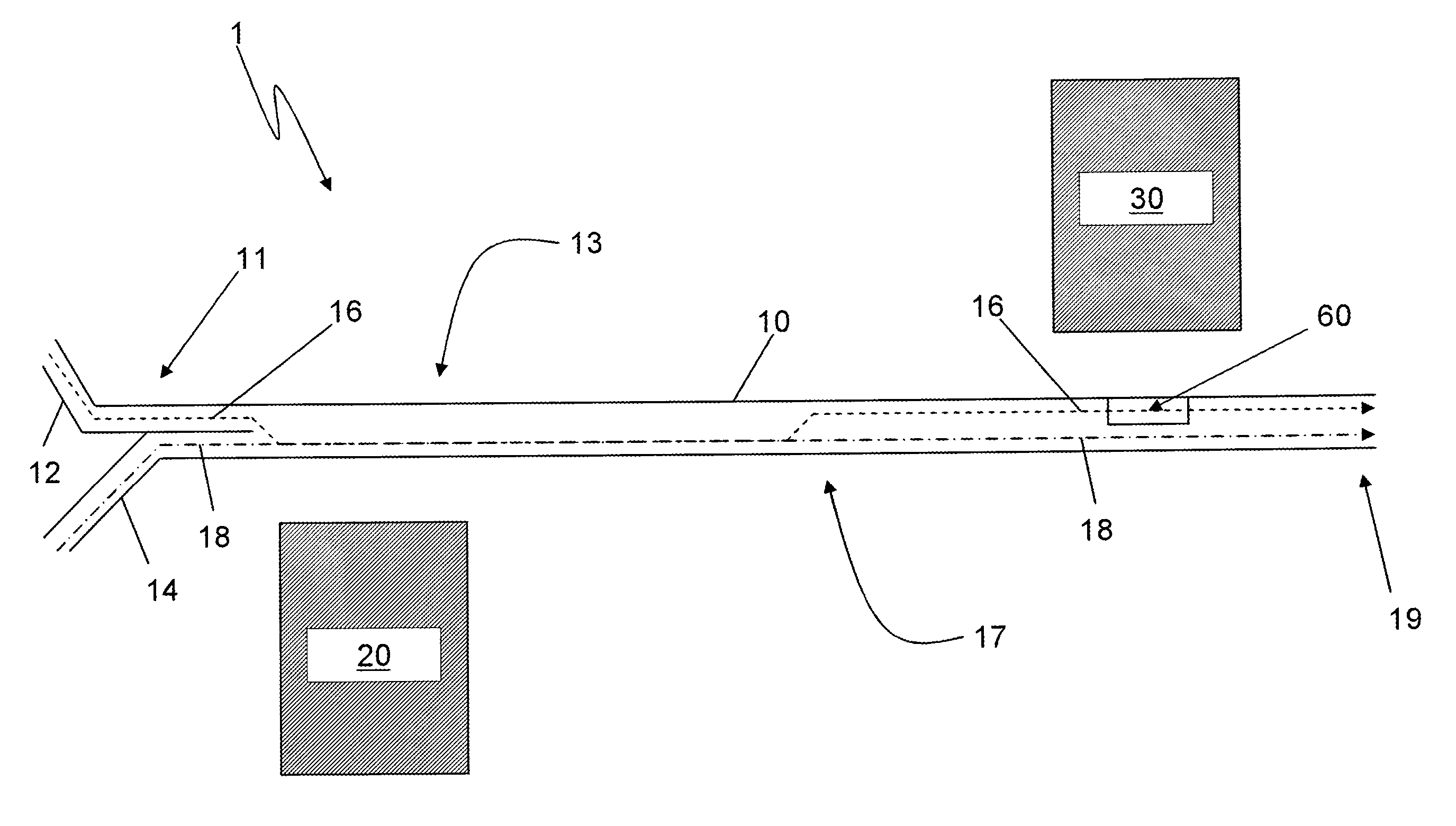
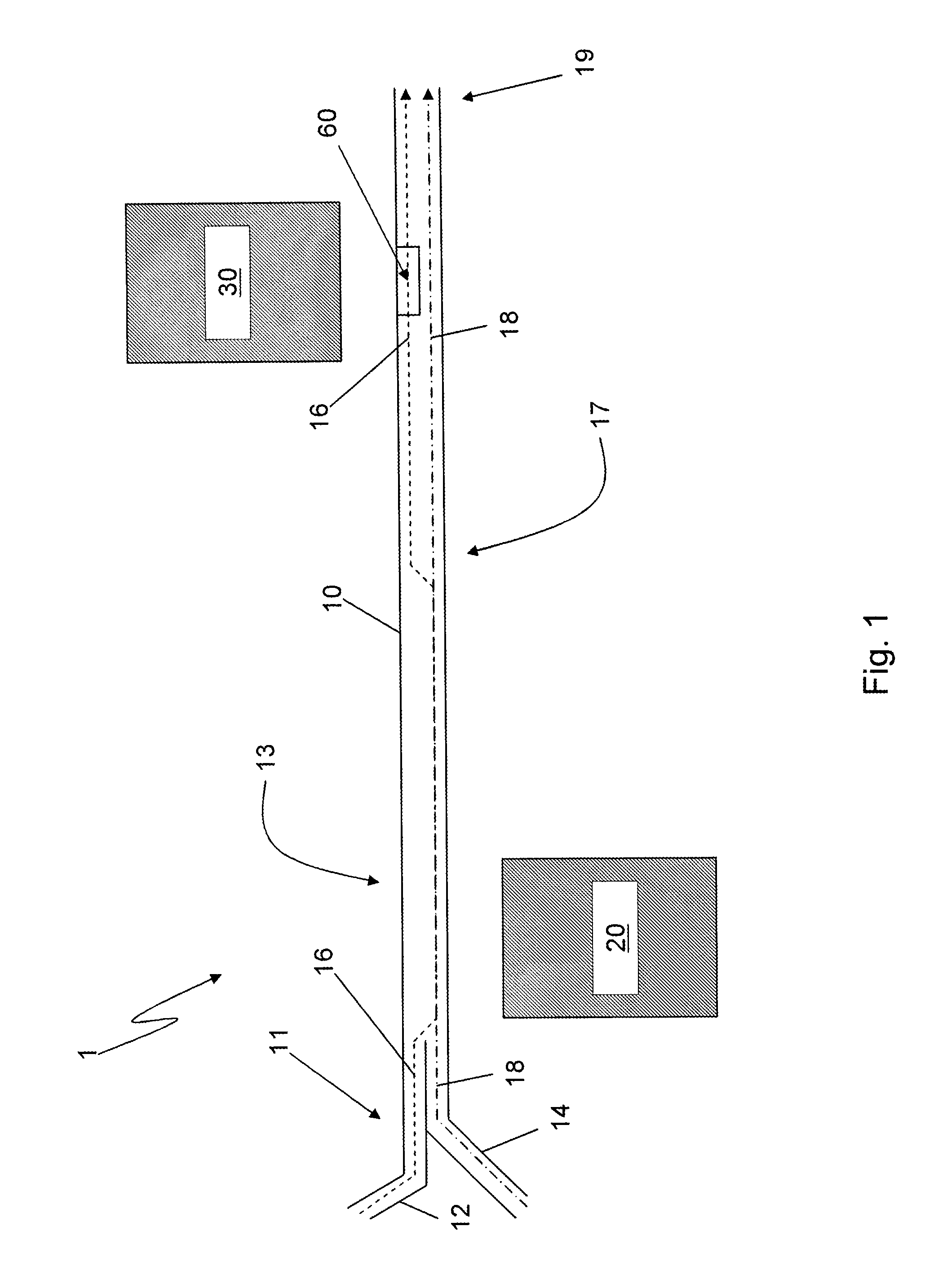
[0042]FIG. 1 is a top plan view illustrating one aspect broadly employed by various embodiments. A detection device 1 includes a fluidic channel 10, a first magnet 20 and a second magnet 30. The channel 10 has an upstream end 11 and a downstream end 19 as defined by fluid flowing within the channel 10. The channel 10 is a microfluidic channel, and may be, for example, about 300 μm wide and 20 μm deep, although other dimensions are certainly possible. Dimensions of the channel 10 may depend, for example, upon the strength of the magnets 20, 30 used, in which wider channels 10 may require stronger magnets 20, 30. The depth of the channel 10 may be determined by, for example, the depth of field of the detection equipment and the size of the magnetic beads used. Typically, the maximum width of the channel 10 is less than 1 mm. The channel 10 also includes a first side 13 and a second side 17, which respectively run along the length of the channel 10 and are preferably defined in part by...


PUM

PropertyMeasurementUnit
concentrationaaaaaaaaaa
widthaaaaaaaaaa
diameteraaaaaaaaaa

Abstract

Provided is a fluidic device including a main channel, wherein a first inlet fluidly connects to an upstream end of the main channel and introduces magnetic beads into a first side of the main channel. A second inlet is fluidly connected to the upstream end of the main channel and introduces a sample stream into a second side of the main channel. A magnet disposed adjacent to the second side of the main channel pulls the magnetic beads towards a sidewall of the second side, and thus into the sample stream. The beads continue through an extended incubation channel before entering a return channel. The return channel includes a detection region. Also provided is a multi-layer micro-fluidic assay device. An assay method that utilizes a microfluidic assay device is provided as well.

Description

CROSS-REFERENCE TO RELATED APPLICATIONS[0001]This application is the Continuation-in-Part of U.S. patent application Ser. No. 13 / 123,547, filed Feb. 5, 2011, which was the U.S. National Phase of International Patent Application Serial No. PCT / US09 / 38880, filed Mar. 31, 2009, which claims the benefit of U.S. Provisional Patent Application Ser. No. 61 / 104,468, filed on Oct. 10, 2008, all of which are incorporated herein by reference in their entireties.STATEMENT REGARDING FEDERALLY SPONSORED RESEARCH[0002]This invention was made with government support under Grant No. 1R21HL084367-01A1 awarded by the National Institutes of Health. The government has certain rights in the invention.FIELD OF THE INVENTION[0003]Various aspects of the invention relate generally to detection methods and devices that employ microfluidics. More particularly, various embodiments disclose devices and related methods that employ paramagnetic beads and magnets disposed along a fluidic channel to detect an analyt...

Claims


Application Information

Patent Timeline
Patent Type & Authority Applications(United States)
IPC IPC(8): G01N21/64G01N21/75G01N33/53
CPCG01N21/05G01N21/64G01N33/54333G01N33/54366B01L3/502746B01L3/502761G01N2021/0346B01L2300/0816B01L2300/0864B01L2300/0883B01L2400/043B01L2400/084G01N15/1484B01L2200/0652
Inventor SASSO, JR., LAWRENCE A.ZAHN, JEFFREY
Owner RUTGERS THE STATE UNIV
Why Eureka
Try Eureka