Eureka AIR delivers breakthrough ideas for toughest innovation challenges, trusted by R&D personnel around the world.

Dc/dc converter, power converter and control method thereof

a converter and power technology, applied in the field of power electronic devices, can solve the problems of inability to implement the first method, inability to control the power supply of the converter, so as to improve the efficiency of the light supply

Active Publication Date: 2012-10-04
DELTA ELECTRONICS (SHANGHAI) CO LTD
View PDF3 Cites 18 Cited by
  • Summary
  • Abstract
  • Description
  • Claims
  • Application Information

AI Technical Summary

Benefits of technology

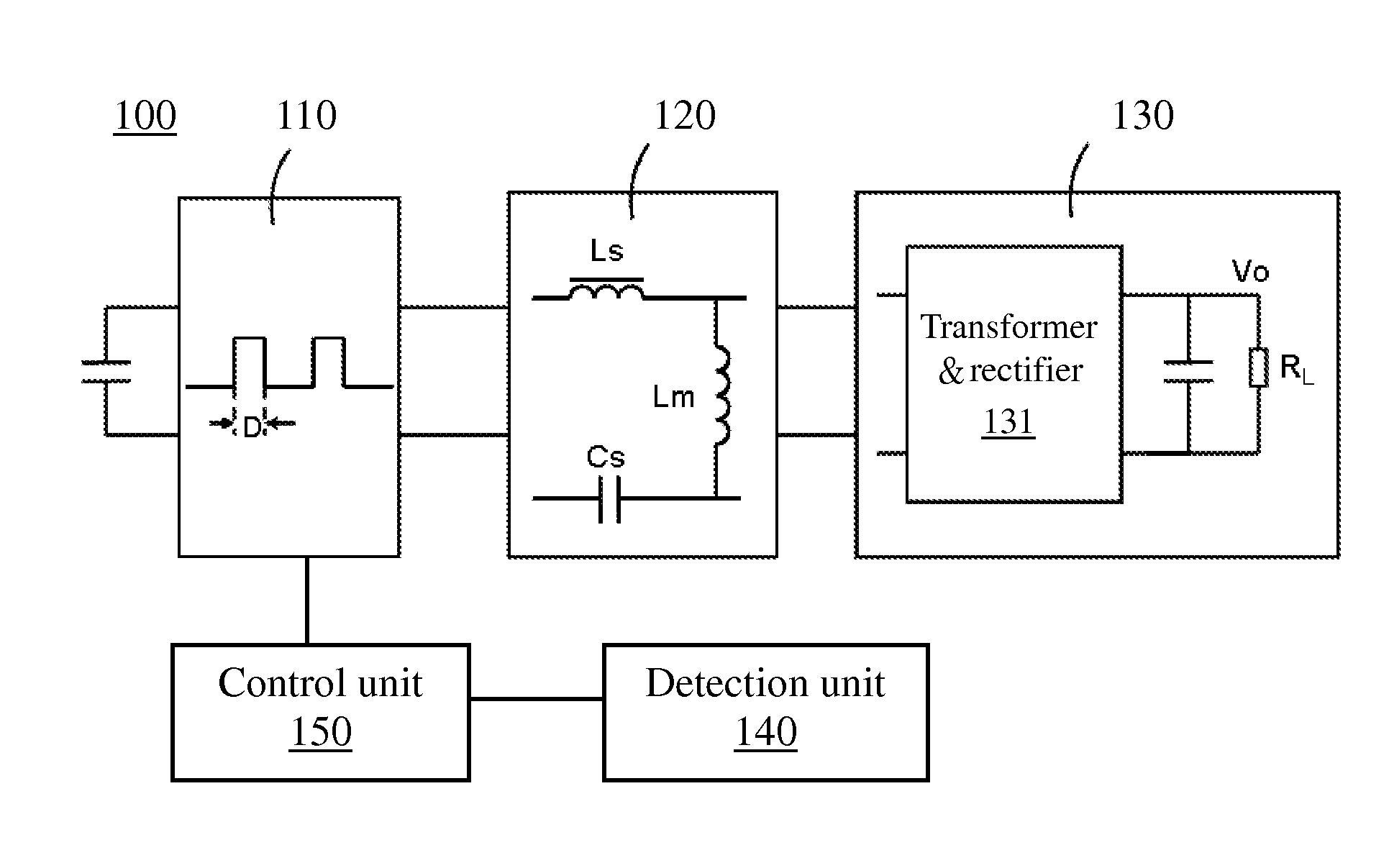
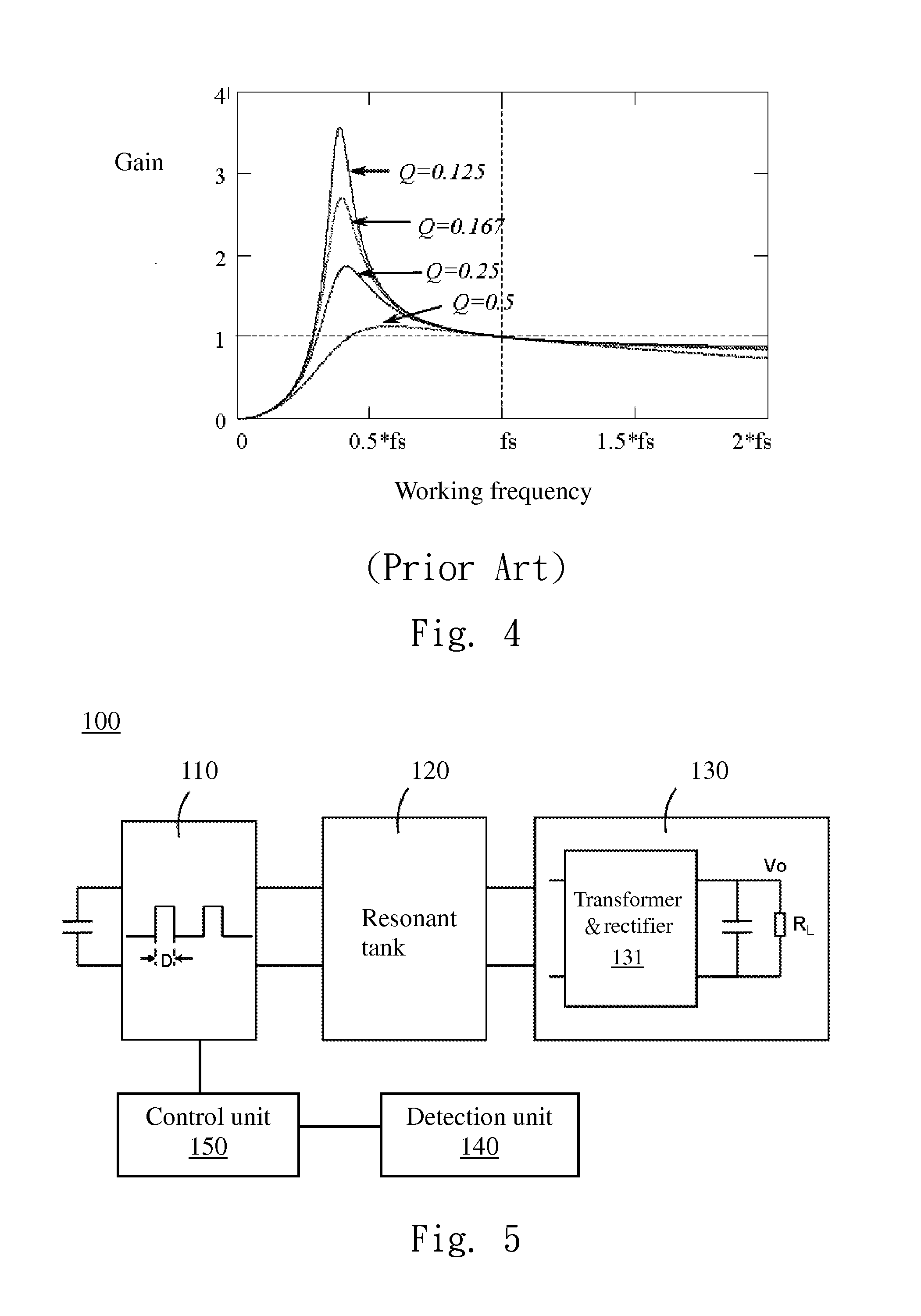
The present patent is about a power converter and a method of controlling it to meet the requirements for high efficiency in the light-load. The power converter includes an output circuit, a rectangular wave generator, a resonant tank, a detection unit, and a control unit. The control unit controls the rectangular wave generator in a hiccup mode to reduce the ratio of the current work period to the stop period. The control unit also changes the duty ratio of the driving pulses during the current work period and keeps on decreasing or increasing the duty ratio of the driving pulses during the following work period to achieve the desired efficiency.

Problems solved by technology

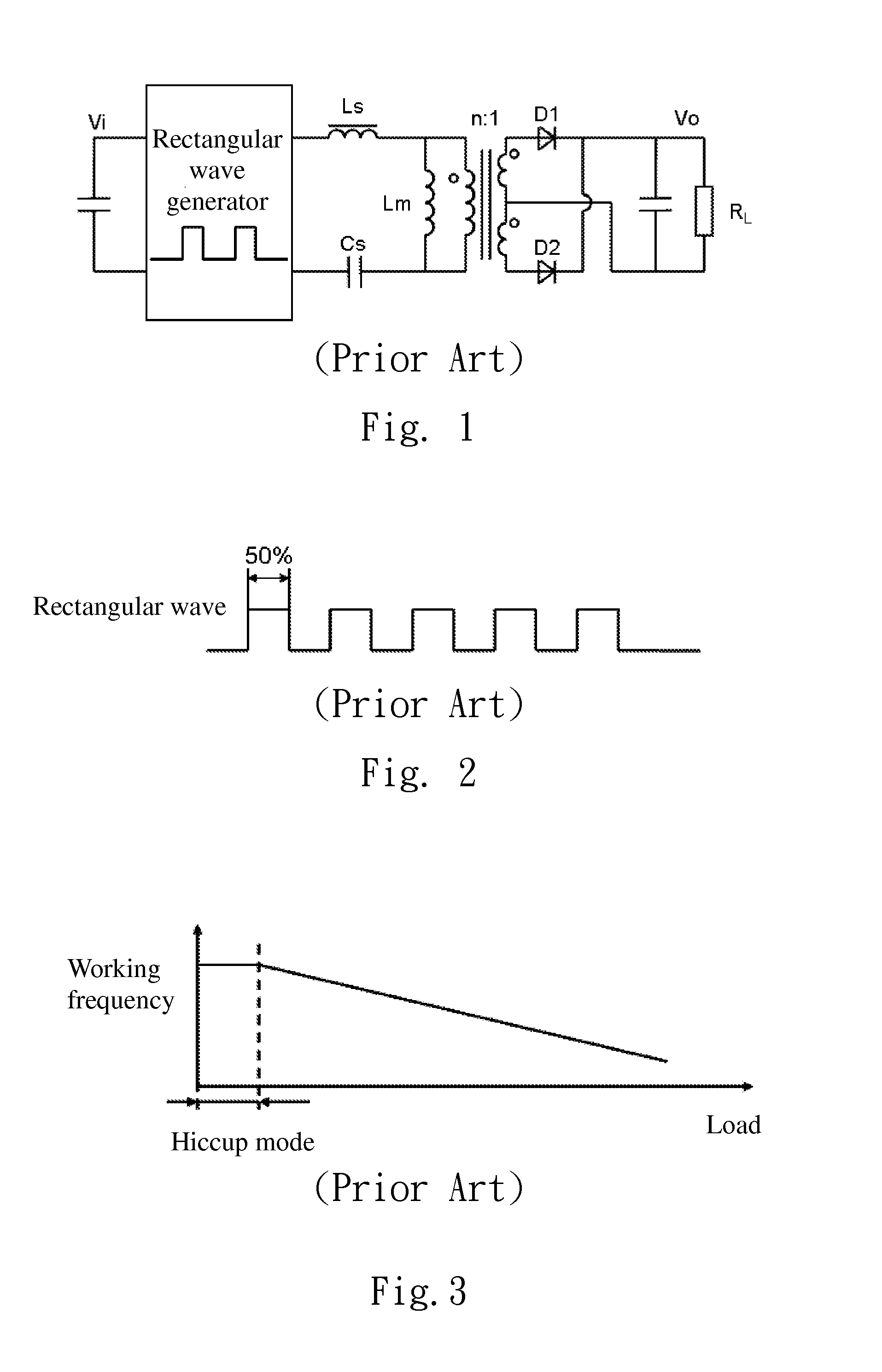
In the resonant circuit, only reducing the operating frequency cannot effectively control the output voltage, and therefore the above first method cannot be implemented.
Therefore, in each work cycle, transmission energy is lower; thus the on-off times of the converter switch is still too much, and excessive switching loss and driving loss per unit time are also higher.
Thus, the second method cannot reach the limit standard for the light-load loss.

Method used


Image

  • Dc/dc converter, power converter and control method thereof
  • Dc/dc converter, power converter and control method thereof
  • Dc/dc converter, power converter and control method thereof

Examples


Embodiment Construction

[0081]In the following detailed description, for purposes of explanation, numerous specific details are set forth in order to attain a thorough understanding of the disclosed embodiments. It will be apparent, however, that one or more embodiments may be practiced without these specific details. In other instances, well-known structures and devices are schematically shown in order to simplify the drawing.

[0082]As used in the description herein and throughout the claims that follow, the meaning of “a”, “an”, and “the” includes reference to the plural unless the context clearly dictates otherwise. Also, as used in the description herein and throughout the claims that follow, the terms “comprise or comprising”, “include or including”, “have or having”, “contain or containing” and the like are to be understood to be open-ended, i.e., to mean including but not limited to. As used in the description herein and throughout the claims that follow, the meaning of “in” includes “in” and “on” un...


PUM


Abstract

A DC / DC converter, a power converter and a control method thereof are disclosed, wherein the DC / DC converter includes an output circuit, a rectangular wave generator, a resonant tank, a detection unit and a control unit. The output circuit has a load. The rectangular wave generator converts an input voltage into driving pulses. The resonant tank provides a first voltage based on the driving pulses for the output circuit. The detection unit detects a signal related to a state of the load. When the state of the load is a light-load or a no-load, the control unit controls the rectangular wave generator in a hiccup mode to reduce a ratio of a work period to a stop period, or makes that number of the driving pulses within the current work period is less than the number of the driving pulses when a duty ratio is 50%.

Description

CROSS-REFERENCE TO RELATED APPLICATION[0001]This application claims the priority benefit of U.S. Provisional Application Ser. No. 61 / 468,215, filed Mar. 28, 2011, which is herein incorporated by reference.BACKGROUND[0002]1. Technical Field[0003]The present disclosure relates to power electronic, and more particularly, a power converter and a control method thereof.[0004]2. Description of Related Art[0005]In recent years, with the fast development of the energy conservation technology, more and more customers desire that a switching-mode converter can achieve high conversion efficiency in a wide load range, so improving the efficiency of this converter in a light-load or a no-load is also very important. In this regard, the International Energy Agency (IEA), the United States and Europe and other countries and organizations have been established or are establishing standards to limit a loss of the switching-mode converter in the light-load or the no-load.[0006]By using resonant conve...

Claims


Application Information

Patent Timeline
Patent Type & Authority Applications(United States)
IPC IPC(8): H02M3/335H02M1/00
CPCH02M3/33569H02M2001/0035Y02B70/16Y02B70/1433Y02B70/1491H02M2001/0058Y02B70/10H02M1/0035H02M1/0058H02M3/33573H02M3/33571H02M3/01
Inventor HU, PEI-QINGJIN, HONG-YUANGAN, HONG-JIANYING, JIAN-PING
Owner DELTA ELECTRONICS (SHANGHAI) CO LTD
Why Eureka
Eureka Blog
Learn More