
Nanometer-scale optical imaging by the modulation tracking (MT) method

a technology of optical imaging and modulation tracking, applied in the direction of optical elements, distance measurement, instruments, etc., can solve the problems of inability to measure the clustering dynamics of proteins using nano-imaging optical methods, and the fluorescence intensity alone cannot be used to determine the distance of the spot from the fluorescent surfa

Active Publication Date: 2012-10-04
RGT UNIV OF CALIFORNIA
View PDF10 Cites 7 Cited by
  • Summary
  • Abstract
  • Description
  • Claims
  • Application Information

AI Technical Summary

Benefits of technology

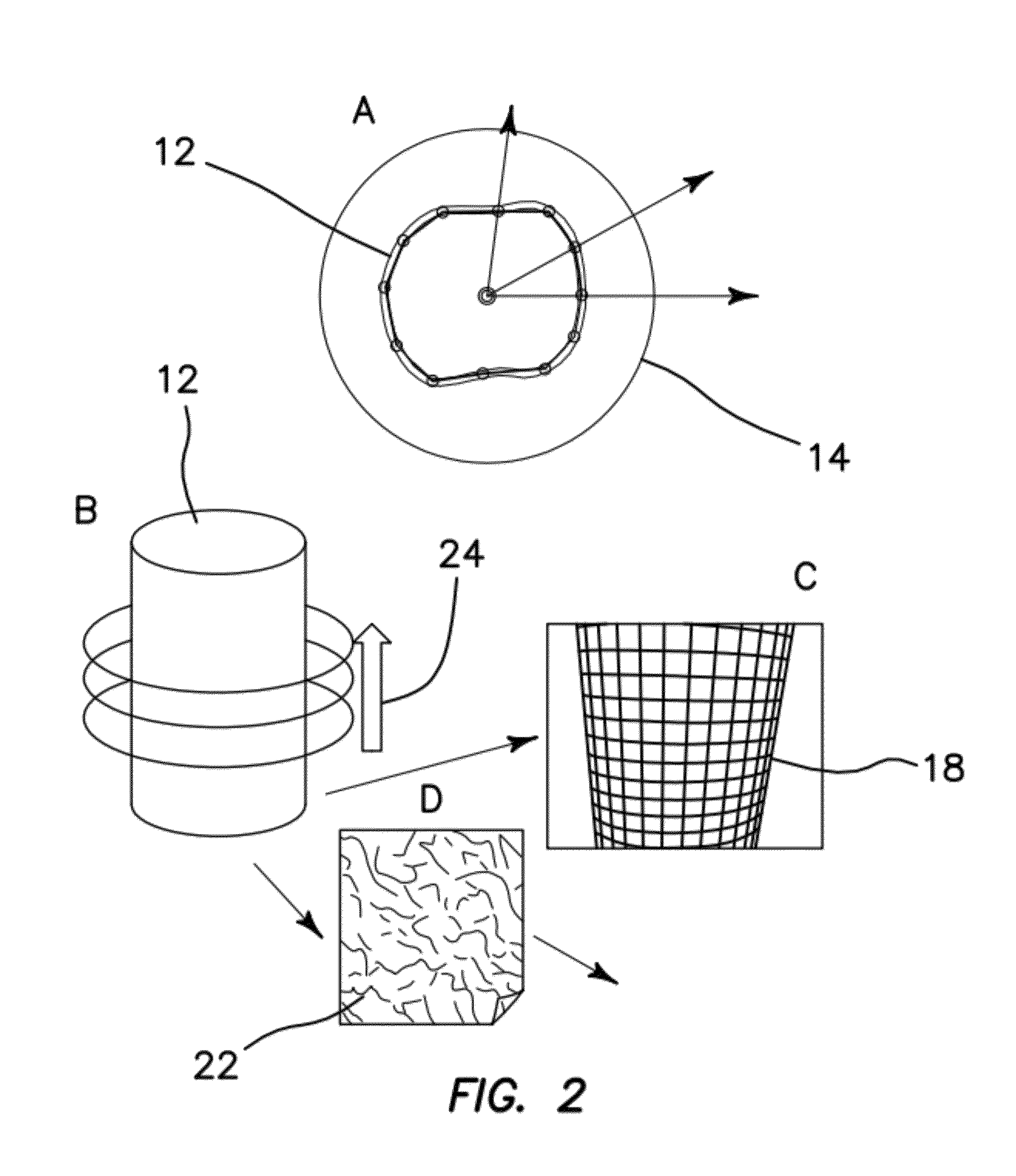
[0008]The illustrated embodiments are directed to an optical imaging method which does not scan the sample with a predetermined pattern. Instead, the illustrated embodiments are based on a feedback principle in which the path followed by the laser spot is decided during the laser scan according to the shape of the features of the object which is being scanned. The feedback algorithm is designed to surf a laser spot with a known point spread function at a constant distance from a fluorescent surface. Since we know the position of the laser spot, its point spread function, and the distance from the surface, we can reconstruct the shape of the object. The uncertainty in the determination of the shape of the object depends on the error in the determination of the position of the laser spot, which is generally in the nanometer range. This feedback imaging approach produces high quality three dimensional images in seconds and does not require sample fixation.

Problems solved by technology

Therefore, the fluorescence intensity alone cannot be used to determine the distance of the spot from the fluorescent surface.
None of the current nano-imaging optical methods are capable of measuring the clustering dynamics of proteins on the surface of rapidly moving (on the second time scale) microvilli.

Method used


Image

  • Nanometer-scale optical imaging by the modulation tracking (MT) method
  • Nanometer-scale optical imaging by the modulation tracking (MT) method
  • Nanometer-scale optical imaging by the modulation tracking (MT) method

Examples


Embodiment Construction

[0050]The illustrated embodiments include an optical imaging method for producing nanometer-resolved three dimensional images of very small and moving features in live cells and in a matter of seconds. The method keeps the laser spot at a constant distance from a fluorescent surface using feedback control. The distance from the surface is determined in real time during the acquisition. Since the position of the laser spot and the distance from the surface is known, the shape of the object can be reconstructed.

[0051]One of the objects of the illustrated embodiments is to image small and sparse features of live cells. These features can be cell protrusions, typical of cell types like neurons, protrusion forming during cell movements or other typical cellular structures like microvilli. The shape of these features are reconstructed with nanometer resolution and the localization of specific molecules mapped on their surface. This approach to nano-imaging allows us to perform fluorescenc...


PUM


Abstract

An optical imaging method based on a feedback principle in which the specific scan pattern is adapted according to the shape of the sample. The feedback approach produces nanometer-resolved three dimensional images of very small and moving features in live cells and in a matter of seconds. Images of microvilli in live cultured opossum kidney cells expressing NaPi co-transporter proteins with different GFP constructs and images of cell protrusions in a collagen matrix are produced with a resolution of about 20 nm. Along cell protrusions in three dimensional cellular adhesions could be identified to the extracellular matrix.

Description

RELATED APPLICATIONS[0001]The present application is related to U.S. Provisional Patent Application Ser. No. 61 / 469,715, filed on Mar. 30, 2011, which is incorporated herein by reference and to which priority is claimed pursuant to 35 USC 119.GOVERNMENT RIGHTS[0002]This invention was made with Government support under Grant Nos. P41-RR003155 and P50-GM076516 awarded by the National Institutes of Health. The Government has certain rights in the invention.BACKGROUND[0003]1. Field of the Technology[0004]The disclosure relates to the field of optical methods for super-resolution imaging of live cells, specifically to an optical imaging method based on a feedback principle in which the specific scan pattern is adapted according to the shape of the sample which produces nanometer-resolved three dimensional images of very small and moving features in live cells and in a matter of seconds.[0005]2. Description of the Prior Art[0006]Several optical microscopy techniques have been previously d...

Claims


Application Information

Patent Timeline
IPC IPC(8): G01C3/08G01B11/24
CPCB82Y35/00G01B9/04G02B2207/113G02B21/0012G01N21/6458
Inventor LANZANO, LUCADIGMAN, MICHELLEGRATTON, ENRICO
Owner RGT UNIV OF CALIFORNIA
Learn More