
Dual-polarization omnidirectional antenna

Inactive Publication Date: 2012-10-04
SHANDONG UNIV OF SCI & TECH
View PDF1 Cites 7 Cited by
  • Summary
  • Abstract
  • Description
  • Claims
  • Application Information

AI Technical Summary

Benefits of technology

[0005]In order to meet the above requirements, an object of the present invention is to provide a dual-polarization omnidirectional antenna having a compact structure and two polarizations of balanced gains.
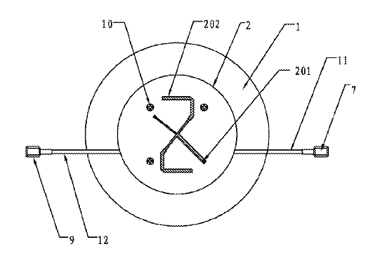
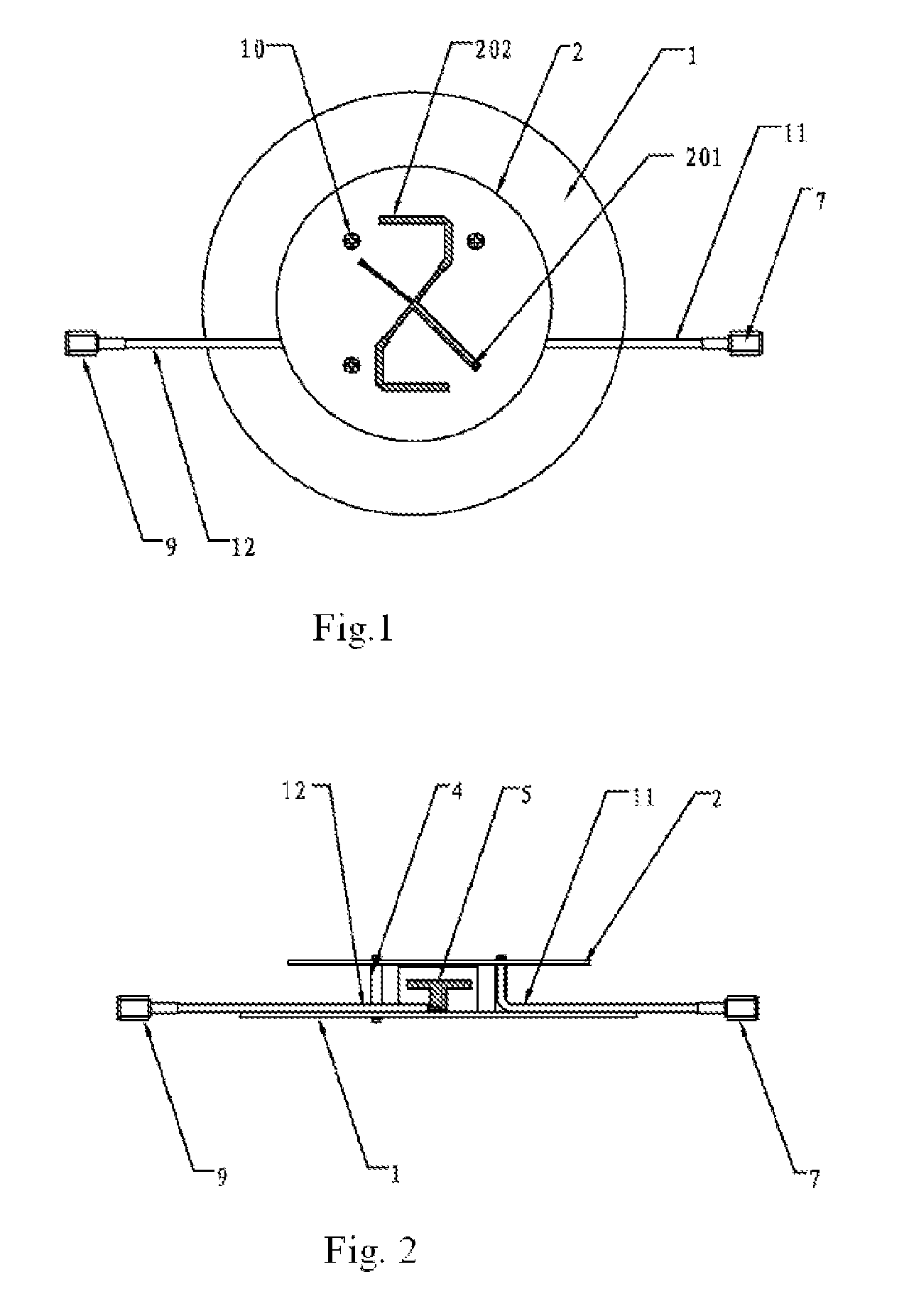
[0014]The dual-polarization omnidirectional antenna of the present invention has following advantages. A radiating oscillator, a reflecting base plate, a metallic supporting pillar, a T-shaped probe, outputting coaxial cables and a mixing ring further provided in a preferred embodiment of the present invention form a dual-polarization omnidirectional antenna polarized at ±45 degrees, under the condition of guaranteeing basic electrical performance, which greatly simplifies a structure of an antenna; meanwhile, the present invention adopts a structure of a round patch of a radiating oscillator, which effectively balances a performance of two polarizations to accomplish basically equal gains of the two polarizations.

Problems solved by technology

Although the conventional technology of the dividing network has matured, the circular-polarization antenna usually has big volume, which complicates the structure of the antenna and leads to large difference in gains of the two polarizations.
Therefore, the circular-polarization antenna is restricted in many application fields.
For dual-polarization omnidirectional antennas, it is relatively difficult to accomplish a horizontal omnidirectional antenna, and thus it is more necessary to develop the dual-polarization omnidirectional antenna polarized at ±45 degrees.

Method used


Image

  • Dual-polarization omnidirectional antenna
  • Dual-polarization omnidirectional antenna
  • Dual-polarization omnidirectional antenna

Examples


Embodiment Construction

[0024]The present invention adopts a form that two polarizations share a radiant round patch. In order to further illustrate a dual-polarization omnidirectional antenna of the present invention, more detailed description combined with preferred embodiments is following.

[0025]A first preferred embodiment

[0026]Referring to FIG. 1 and FIG. 2 of the drawings, the dual-polarization omnidirectional antenna comprises a reflecting base plate 1, a radiating oscillator 2, a metallic supporting pillar 4, a T-shaped probe 5, a first RF connector 7, a second RF connector 9, a first outputting coaxial cable 11 and a second outputting coaxial cable 12.

[0027]Referring to FIG. 3a and FIG. 3b of the drawings, the radiating oscillator 2 comprises a two-side copper-coated dielectric plate. An upper layer of the two-sides copper-coated dielectric plate of the radiating oscillator 2 is etched into a one-to-two feed dividing network 20 which is accomplished by a conventional art; a lower layer of the two-...


PUM


Abstract

A dual-polarization omnidirectional antenna includes a reflecting base plate, a radiating oscillator, outputting coaxial cables, RF connectors, a metallic supporting pillar and a T-shaped probe. The radiating oscillator has an upper layer provided with a one-to-two feed dividing network and a lower layer provided with a round patch; the T-shaped probe is welded with the round patch. A mixing ring is arranged on the reflecting base plate; two RF connectors are respectively connected with a first port and a second port of the mixing ring; an inner conductor of a first outputting coaxial cable has a first end connected with the feed dividing network and a second end connected with a third port of the mixing ring; an inner conductor of another outputting coaxial cable has a first end connected with the T-shaped probe and a second end connected with a fourth port of the mixing ring.

Description

BACKGROUND OF THE PRESENT INVENTION[0001]1. Field of Invention[0002]The present invention relates to an antenna in a field of mobile communications, and more particularly to an antenna having al least two radiating patterns.[0003]2. Description of Related Arts[0004]A conventional dual-polarization omnidirectional antenna mainly adopts the combination of vertical polarization and horizontal polarization. Most of the conventional dual-polarization omnidirectional antennas accomplish omnidirectional beams by arranging several oscillators in a circle. Although the conventional technology of the dividing network has matured, the circular-polarization antenna usually has big volume, which complicates the structure of the antenna and leads to large difference in gains of the two polarizations. Therefore, the circular-polarization antenna is restricted in many application fields. Meanwhile, in the actual application, particularly in the field of mobile communications, the vertical-polarizat...

Claims


Application Information

Patent Timeline
IPC IPC(8): H01Q19/10
CPCH01Q9/0457H01Q9/0435H01Q25/001
Inventor WANG, ZHUOPENGFU, HONGQUANCHANGHONG, XIAO
Owner SHANDONG UNIV OF SCI & TECH
Learn More