
Power Routing in Standard Cell Designs

a technology of power rails and standard cells, applied in the direction of logic circuits using specific components, pulse techniques, instruments, etc., can solve the problems of waste, increase the height of cells, and remove the retention rail dedicated to just one row of cells, so as to reduce the size of the integrated circuit created, the effect of reducing the size of the cells

Active Publication Date: 2012-10-04
SYNOPSYS INC
View PDF10 Cites 49 Cited by
  • Summary
  • Abstract
  • Description
  • Claims
  • Application Information

AI Technical Summary

Benefits of technology

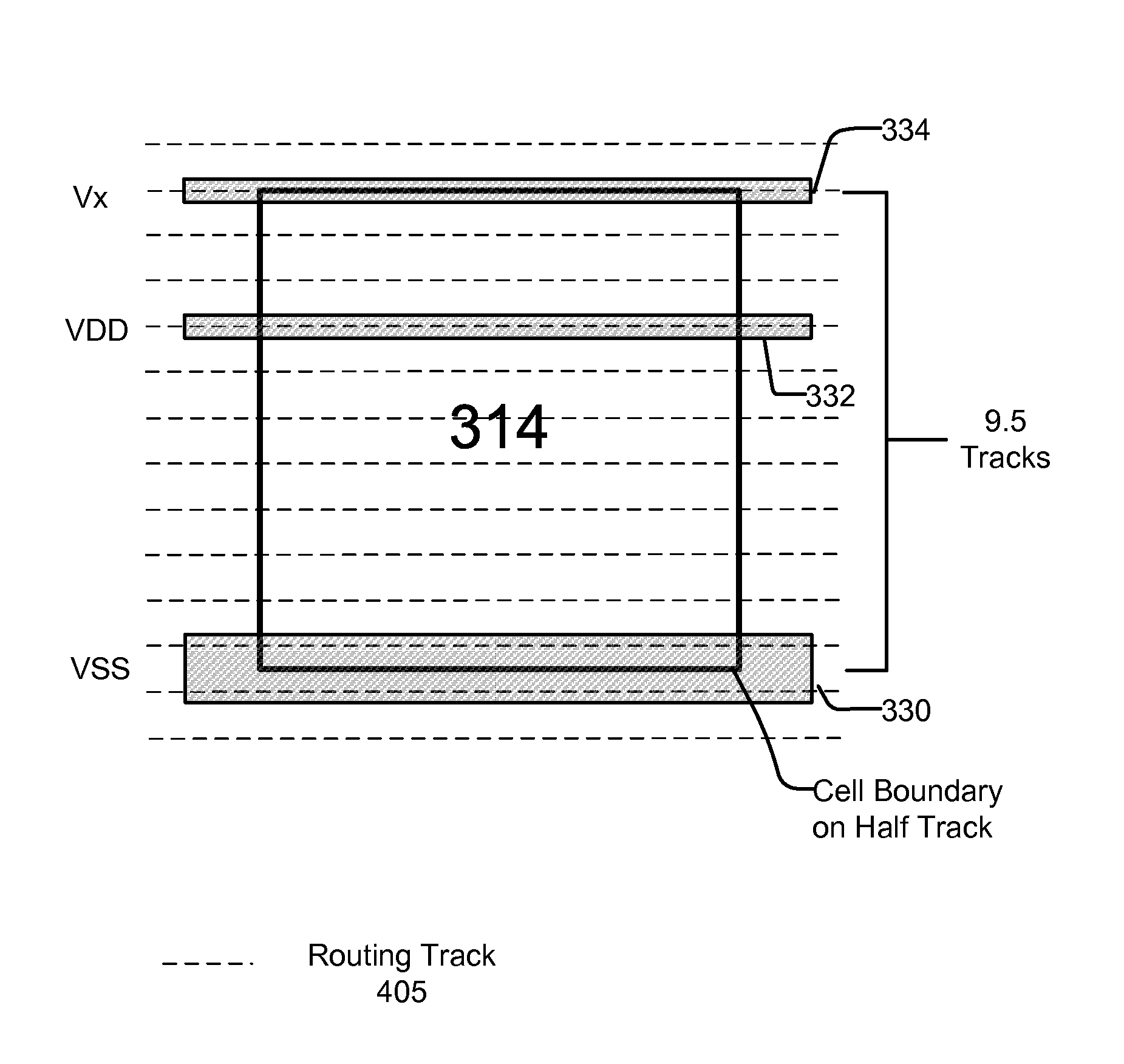
The present patent relates to a cell-based architecture for an integrated circuit design. The architecture includes a row of cell instances with a first power rail along one boundary, a second power rail along another boundary that is wider than the first power rail, and a third power rail across the interior of a second row of cells. This arrangement allows for efficient use of power and current in the circuit. The patent also includes a computer-readable medium with a cell library for use in integrated circuit design. The technical effect of this architecture is to improve the performance and efficiency of integrated circuits.

Problems solved by technology

However, adding a dedicated retention rail to a cell increases the cell height or takes away a routing track which could otherwise be used to route global signals for connecting the pins of the cells.
Additionally, having a retention rail dedicated to just one row of cells is wasteful because retention rails only carry a fraction of the current of a primary power rail such as VDD.

Method used


Image

  • Power Routing in Standard Cell Designs
  • Power Routing in Standard Cell Designs
  • Power Routing in Standard Cell Designs

Examples


Embodiment Construction

[0020]The Figures (FIGS.) and the following description relate to preferred embodiments by way of illustration only. It should be noted that from the following discussion, alternative embodiments of the structures and methods disclosed herein will be readily recognized as viable alternatives that may be employed without departing from the principles of what is claimed.

[0021]Reference will now be made in detail to several embodiments, examples of which are illustrated in the accompanying figures. It is noted that wherever practicable similar or like reference numbers may be used in the figures and may indicate similar or like functionality. The figures depict embodiments of the disclosed system (or method) for purposes of illustration only. One skilled in the art will readily recognize from the following description that alternative embodiments of the structures and methods illustrated herein may be employed without departing from the principles described herein.

[0022]Embodiments inc...


PUM


Abstract

A cell-based architecture for an integrated circuit. A row of cell instances borders a first adjacent row of cell instances along a first boundary and a second adjacent row of cell instances along a second boundary. A first power rail (e.g., carrying an auxiliary voltage) extends along the first boundary. A second power rail (e.g., VSS) extends along the second boundary. The second power rail is wider than the first power rail. Additionally, a third power rail (e.g., VDD) extends across the interior of the second row of cells.

Description

CROSS-REFERENCE TO RELATED APPLICATIONS[0001]This application claims priority under 35 U.S.C. §119(e) to U.S. Provisional Patent Application Ser. No. 61 / 469,489, “Power Routing in Standard Cell Designs,” filed Mar. 30, 2011, which is incorporated herein by reference in its entirety.BACKGROUND[0002]1. Field of Art[0003]The disclosure generally relates to the field of electronic design automation (EDA), and more specifically to routing of power rails for a standard cell that is used to design integrated circuits (ICs).[0004]2. Description of the Related Art[0005]Computer-aided cell-based design has been developed for quickly designing large scale ICs such as application specific integrated circuits (ASICs) and gate arrays. The cell is a circuit that has been pre-designed and pre-verified as a building block. Design technologies known as standard cell and gate array use different types of such building blocks. In a standard cell design, each distinct cell in a library may have unique g...

Claims


Application Information

Patent Timeline
Patent Type & Authority Applications(United States)
IPC IPC(8): H01L25/00G06F17/50
CPCG06F2217/78G06F17/5077G06F30/394G06F2119/06G06F30/00
Inventor SHERLEKAR, DEEPAK D.
Owner SYNOPSYS INC
Learn More