
Instantaneous single click perpetual date mechanism

a date mechanism and instantaneous single-click technology, applied in mechanical time indication, instruments, visual indication, etc., can solve the problems of affecting the accuracy of the date mechanism, the adjustment of the two clicks relative to each other is not favorable to precise stopping, and the degree of inertia is significant, so as to achieve the effect of regulating the torque level

Active Publication Date: 2012-09-27
MONTRES BREGUET
View PDF6 Cites 4 Cited by
  • Summary
  • Abstract
  • Description
  • Claims
  • Application Information

AI Technical Summary

Benefits of technology

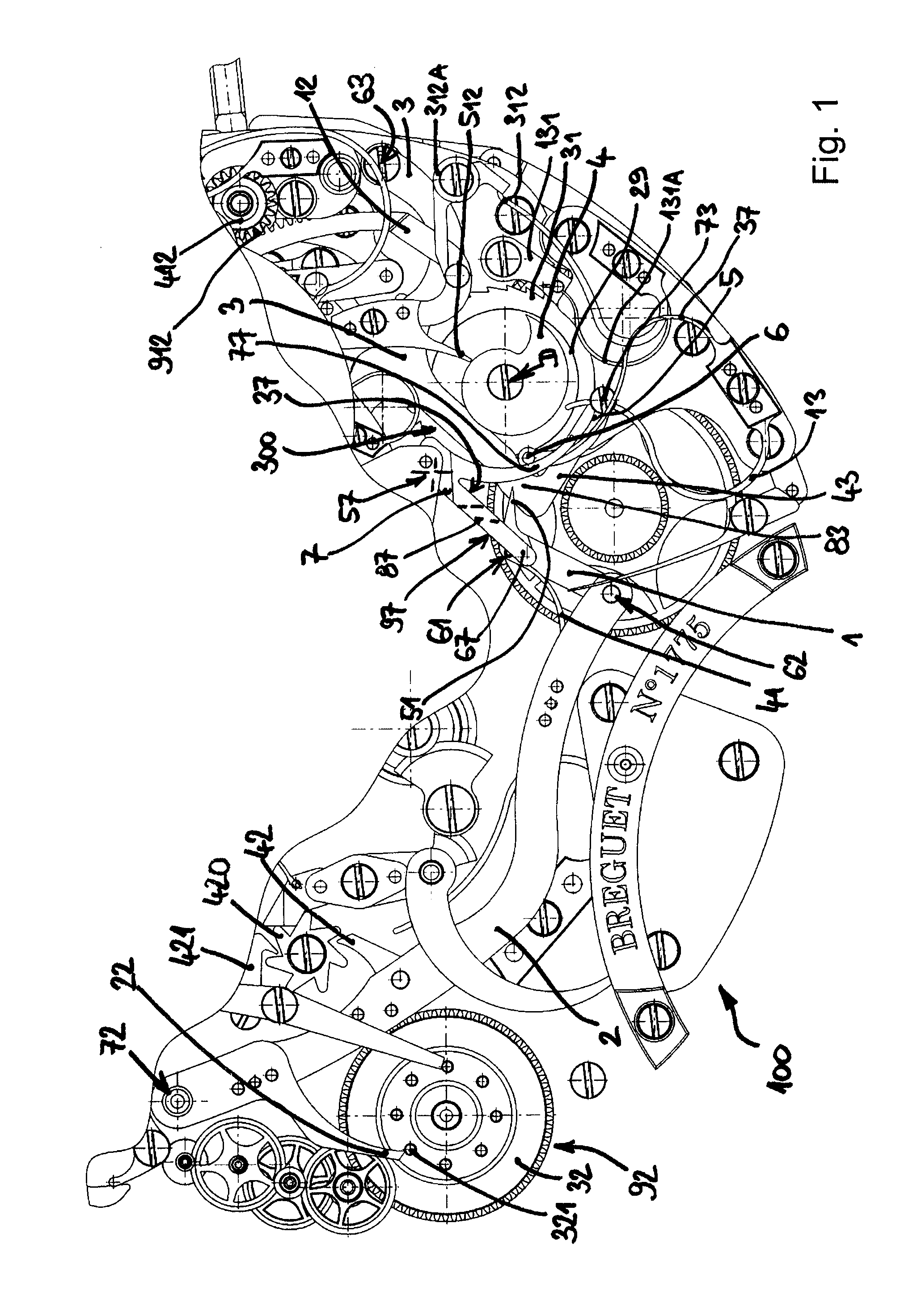
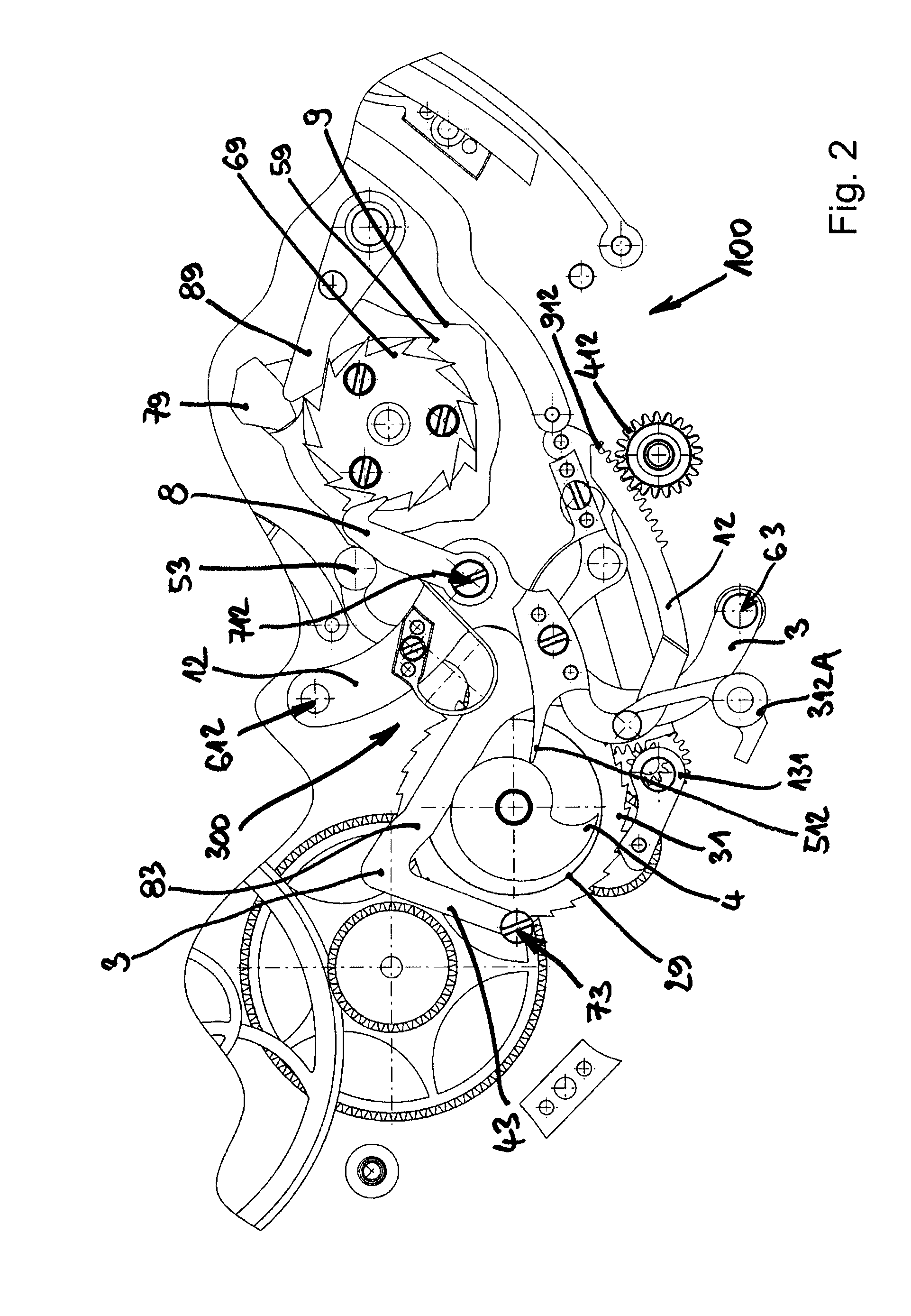
[0022]The invention also proposes to develop a date mechanism which is easier to arrange in a timepiece than known mechanisms, and in particular so that this mechanism can be arranged in a peripheral area of the watch, less congested by the complications.
[0032]The mechanism works when the lever falls and not when it rises. This operation as the lever falls allows an instantaneous operation: the lever rises slowly, especially when there are several days to pass, and operates instantaneously during the return by the action of a spring. A single click drives the number of teeth necessary to adjust the date. The lever does not directly make the day jumps, but winds a spring which performs said jumps, thus the invention regularises the level of torque used by the mechanism.

Problems solved by technology

Indeed, this type of perpetual lever with two clicks and their springs has significant inertia, which is not favourable for precise stopping.
The adjustment of these two clicks relative to each other is, moreover, quite delicate, and sensitive to shocks and any improper operations that the timepiece may undergo, in particular when the user operates the timepiece around midnight.
This problem of inertia is particularly marked in the case of a retrograde date mechanism, where problems of rebound, which are already difficult to limit, are amplified in the event of significant inertia.

Method used


Image

  • Instantaneous single click perpetual date mechanism
  • Instantaneous single click perpetual date mechanism
  • Instantaneous single click perpetual date mechanism

Examples


Embodiment Construction

[0050]The invention presents a date mechanism which is easier to arrange in a timepiece than known mechanisms, and in particular so that this mechanism can be arranged in a peripheral area of the watch, less congested by the complications.

[0051]The invention is described here for the particular case of an instantaneous retrograde date mechanism, but it can be applied to any instantaneous date mechanism.

[0052]The invention concerns a date mechanism 100 for a timepiece 1000, which includes a movement 200.

[0053]This date mechanism 100 includes various isolators and levers, of which the form shown here is only illustrative, and which is essentially imposed by the other complications comprised in the timepiece, and by the necessity of avoiding interference, which may result in more complex forms than required by the actual functions.

[0054]Likewise, it should be understood that the invention can be adapted to any desired periodicity. Those skilled in the art know how to transpose the dail...


PUM


Abstract

Date mechanism (100) for a timepiece (1000) including a movement (200) which daily pivots a lever (2), comprising a perpetual twelve cam (9) with sectors whose depth depends on the duration of the successive months, completing one revolution per year.The mechanism has a single click and includes:a single click finger (1), hinged to said lever (2) and arranged to cooperate with a thirty-one ratchet wheel (31) which pivots integrally with a first thirty-one snail cam (4) arranged to control a date display means (412), and a second cam (29) including a radial finger (29A);a countdown mechanism (300) whose position is determined by said second cam (29), adjusting the number of teeth of said wheel (31) to be activated by said click finger (1) according to the current day and current month;a means of driving said cam (9).

Description

[0001]This application claims priority from European Patent Application No. 11159239.0 filed Mar. 22, 2011, the entire disclosure of which is incorporated herein by reference.FIELD OF THE INVENTION[0002]The invention concerns a date mechanism for a timepiece, which includes a movement arranged to actuate, once a day, a pivoting movement of a perpetual lever, comprised in said date mechanism, said mechanism including a means of driving a perpetual twelve cam, which includes twelve sectors for the successive months of different radial dimensions depending upon the duration of each month, and which completes one revolution per year.[0003]The invention also concerns a timepiece including a movement and including a date mechanism of this type.[0004]The invention concerns the field of horology, and more specifically the field of timepieces including date mechanisms.BACKGROUND OF THE INVENTION[0005]The most conventional date timepieces are described in particular in the work entitled “Les ...

Claims


Application Information

Patent Timeline
IPC IPC(8): G04B19/24
CPCG04B19/2536
Inventor GOELLER, ERIC
Owner MONTRES BREGUET
Learn More