
Emergency piloting by means of a series actuator for a manual flight control system in an aircraft

Active Publication Date: 2012-09-27
AIRBUS HELICOPTERS DEUT GMBH +1
View PDF3 Cites 13 Cited by
  • Summary
  • Abstract
  • Description
  • Claims
  • Application Information

AI Technical Summary

Benefits of technology

[0042]One of the main objects of the invention is to provide an aircraft control architecture that further increases safety in the event of at least one of the flight control systems breaking.
[0044]Furthermore, the invention seeks to avoid increasing the overall weight of the manual flight control system, and possibly even to reduce it, while nevertheless providing increased safety.
[0046]The invention also seeks to avoid increasing and even to decrease the forces the pilot needs to apply to actuate a manual flight control system (in normal operation), while still providing increased safety (in the event of breakage).
[0047]Finally, the invention seeks to mitigate the problems mentioned, while relying on the validity of existing safety analyses, i.e. without requiring major reworking of certifications.

Problems solved by technology

These manual flight control systems are thus relatively long and heavy, in particular for transmitting movements to control changes of attitude in yaw.
Such systems generate friction forces that can be considerable, particularly when the systems are long and / or complex (i.e. include numerous components).
Nevertheless, such electrical flight controls are difficult to implement in practice.
In particular on existing aircraft they give rise to modifications that are extensive and expensive.
Although they are of interest, those documents are in practice poorly adapted to the very particular context of emergency piloting in the event of a break in a flight control of a rotary wing aircraft, e.g. a helicopter.
Such a breakage within a manual flight control system could lead to the aircraft being lost.
Nevertheless, those approaches tend to increase the control forces that need to be applied to the manual flight control system, in particular while it is being controlled in normal mode.

Method used


Image

  • Emergency piloting by means of a series actuator for a manual flight control system in an aircraft
  • Emergency piloting by means of a series actuator for a manual flight control system in an aircraft
  • Emergency piloting by means of a series actuator for a manual flight control system in an aircraft

Examples


Embodiment Construction

[0176]By means of the invention, it is thus possible to obtain an aircraft 1 that implements the emergency piloting method and / or that includes one or more manual flight control systems 7 as described above, regardless of whether the aircraft 1 is a rotary wing aircraft.

[0177]The invention thus proposes a novel and non-obvious use of one or more series actuators 21 in the event of flight controls breaking as emergency piloting means.

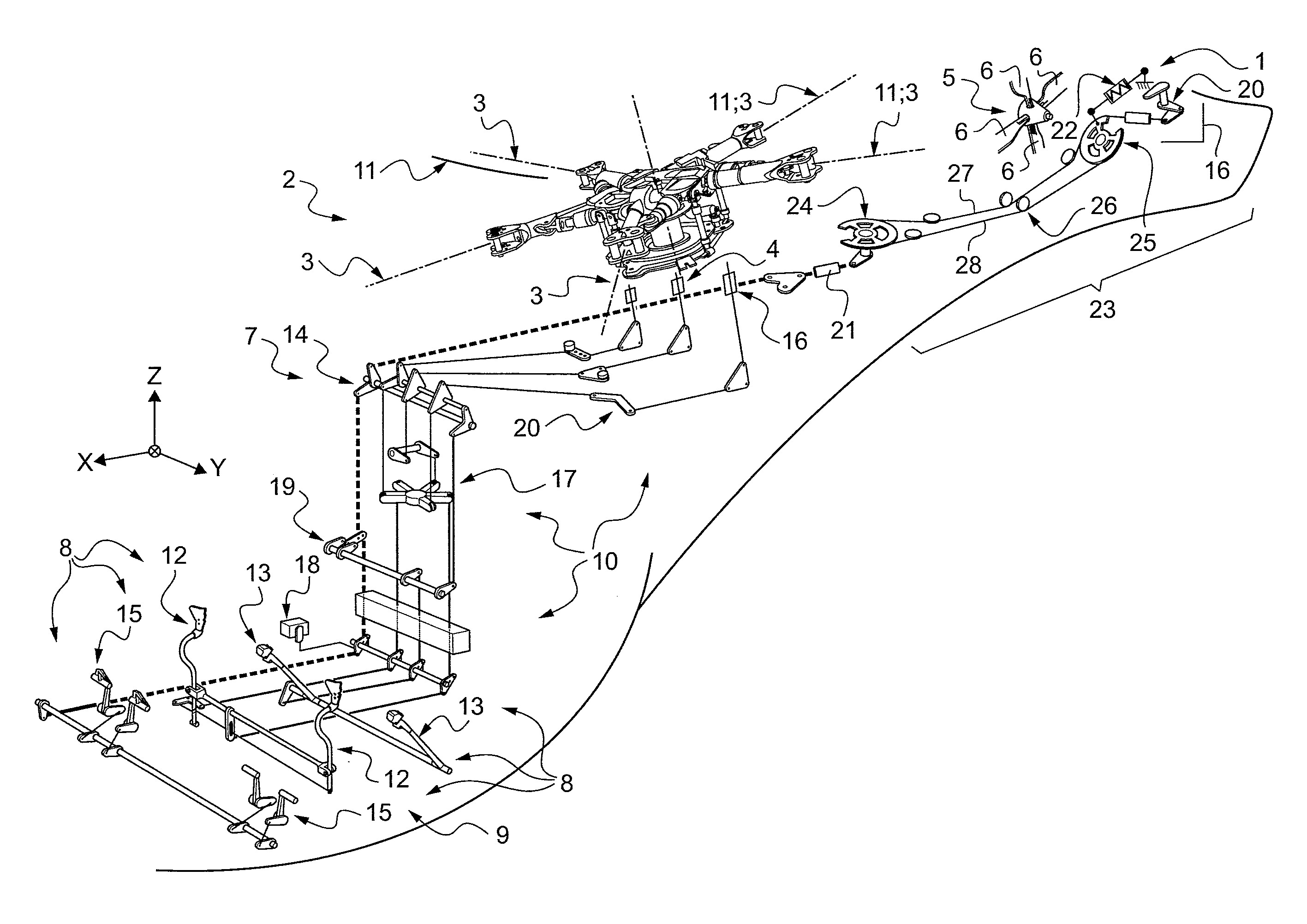
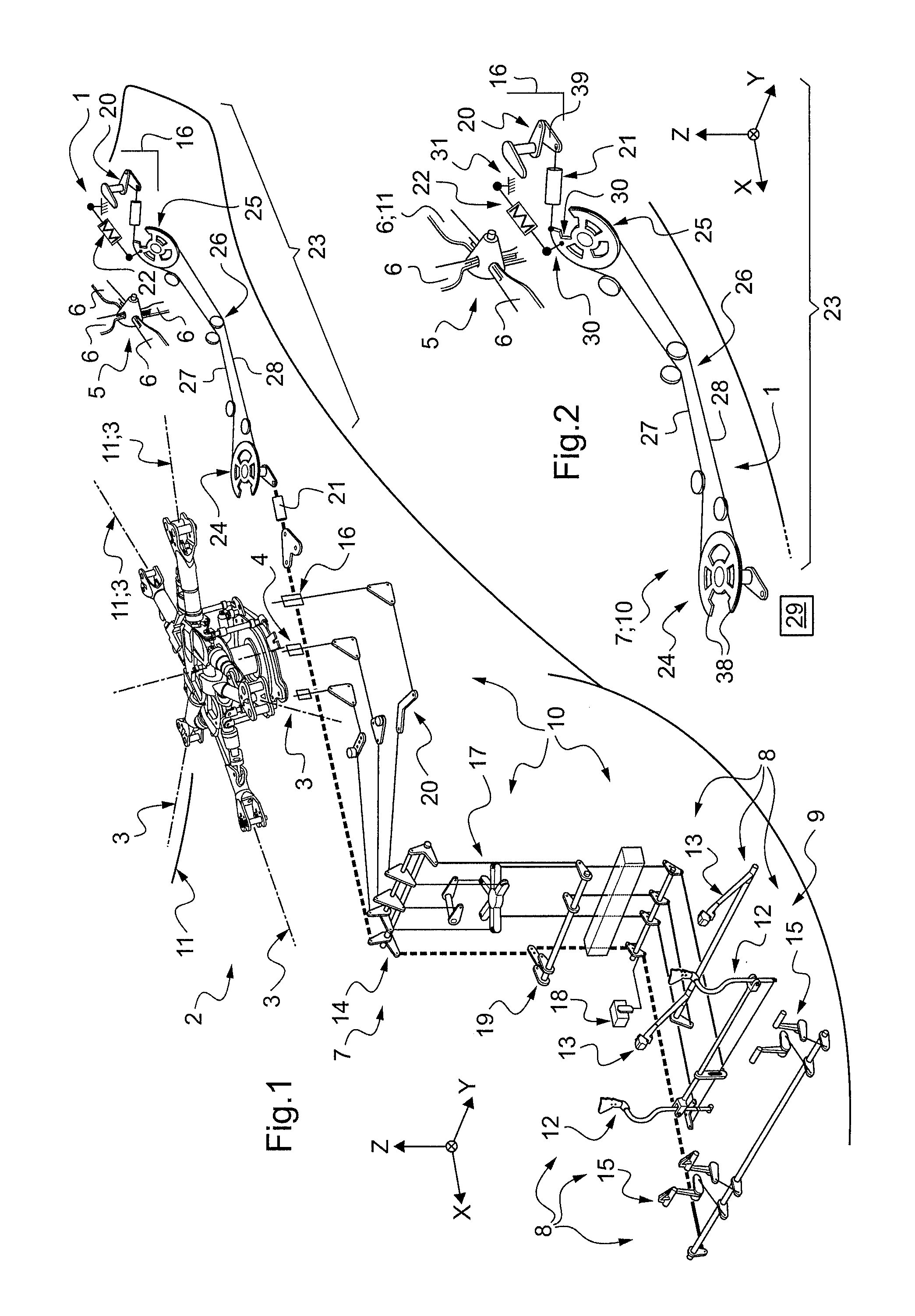
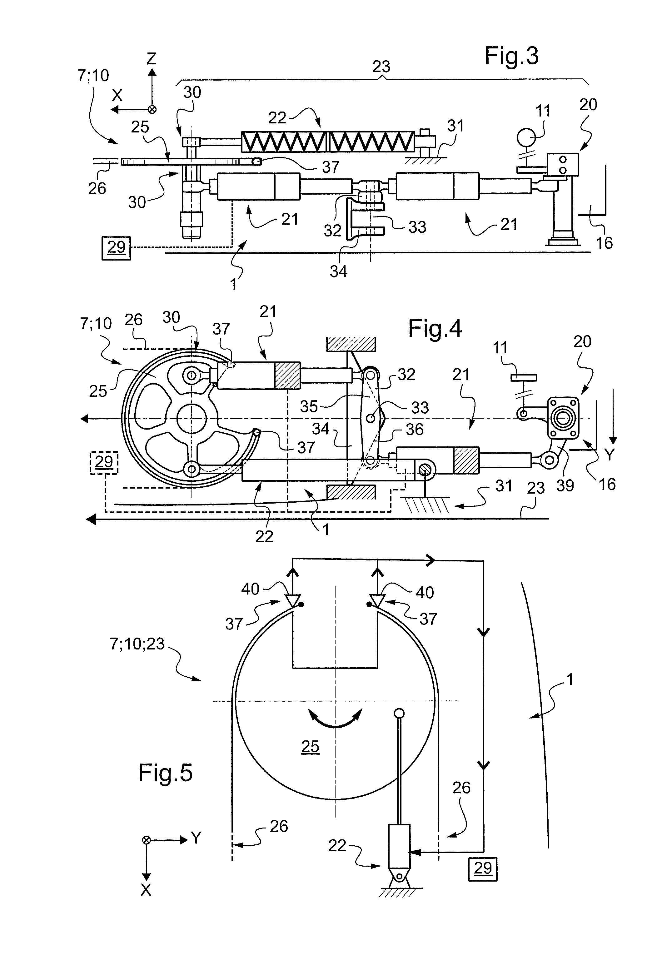
[0178]A flight control breaking can sometimes lead to the aircraft 1 being lost. Certain systems (e.g. the yaw system) may be fitted with a centering rod 22, e.g. upstream from the input quadrant 24. Thus, in the event of a break, it is possible to lock the position of the rudder automatically, e.g. the anti-torque rotor 5 for the yaw system 7, in a predetermined position after the controls have broken.

[0179]Nevertheless, the predetermined return position corresponds to a single flight setting associated with a refuge speed. This may make it necessary to...


PUM


Abstract

For emergency piloting of a manual flight control system (7) of an aircraft (1), in the event of flexible connection means (26) breaking, an upstream control device (8) takes authority over the electronic control unit (29) of series actuator (21). An output pivoting quadrant (25) is subjected by a centering rod (22) to a blocking and centering action. In the event of the system breaking, the output pivoting quadrant (25) forms a bearing point for the series actuator (21), so that an emergency control actuate a airfoil surface (11).

Description

CROSS REFERENCE TO RELATED APPLICATIONS[0001]This application claims priority to EP 11 290147.5 filed on Mar. 25, 2011, the disclosure of which is incorporated in its entirety by reference herein.BACKGROUND OF THE INVENTION[0002](1) Field of the Invention[0003]The present invention relates to the field of the emergency piloting of aircraft.[0004](2) Description of Related Art[0005]Emergency piloting means the pilot maintaining a certain amount of authority over changes in the attitude of the aircraft in the event of one or more of the manual flight control systems that are provided for controlling such changes of attitude in normal operation not operating normally.[0006]Without this being a limitation, the invention is described in its applications to rotary wing aircraft, such as helicopters and other rotorcraft or hybrid craft. The invention also applies to other aircraft having so-called “fixed” wings (airplanes, gliders, or the like).[0007]The flight control systems concerned by...

Claims


Application Information

Patent Timeline
IPC IPC(8): G05D1/00
CPCB64C13/30Y02T50/44B64C27/58B64C13/42Y02T50/40B64C27/56B64C27/59B64C27/78
Inventor CHADUC, BRUNOHELLIO, PATRICKGEMMATI, BERNARDKROK, KARSTEN
Owner AIRBUS HELICOPTERS DEUT GMBH
Learn More