Charge/Discharge Control Device and Power Generation System

Inactive Publication Date: 2012-09-20
SANYO ELECTRIC CO LTD
View PDF2 Cites 31 Cited by
  • Summary
  • Abstract
  • Description
  • Claims
  • Application Information

AI Technical Summary

Benefits of technology

[0015]According to the present invention, the lifetime of the storage portion can be increased while effects of fluctuation in the power generated by the power generator on the power grid are suppressed.

Problems solved by technology

However, the output of power generators utilizing natural energy may change sharply in correspondence with the weather and the like.
This sharp change in the power output of this type of power generators has adverse effects on the degree of stability of the frequency of the linked power grid.
These adverse effects become more pronounced as the number of consumers with power generators utilizing natural energy increases.
However, in the aforementioned Japanese Patent Laying-Open No. 2007-228737, the charge / discharge of the storage portion is performed each time following the fluctuation in the power generated by the power generator, and hence the charging / discharging count is increased so that the lifetime of the storage portion including a secondary cell or the like is disadvantageously decreased.

Method used


Image

  • Charge/Discharge Control Device and Power Generation System
  • Charge/Discharge Control Device and Power Generation System
  • Charge/Discharge Control Device and Power Generation System

Examples


first embodiment

[0050]First, the structure of a power generation system (photovoltaic power generation system 1) according to a first embodiment of the present invention is described with reference to FIGS. 1 to 7.

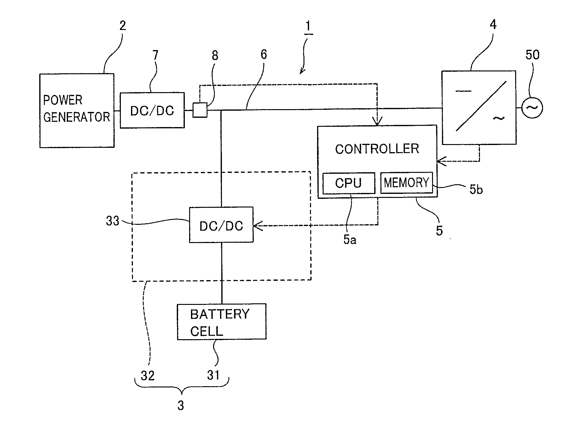
[0051]The photovoltaic power generation system 1 according to the first embodiment of the present invention includes a power generator 2 including a solar cell generating power with sunlight, a battery 3 capable of storing the power generated by the power generator 2, a power output unit 4 connected to a power grid 50, including an inverter outputting the power generated by the power generator 2 and the power stored in the battery 3 to the power grid 50, and a controller 5 controlling charge and discharge of the battery 3. The controller 5 is an example of the “charge / discharge control device” in the present invention.

[0052]A DC-DC converter 7 is serially connected to a DC-side bus 6 connecting the power generator 2 and the power output unit 4. The DC-DC converter 7 has a function of conv...

second embodiment

[0120]Next, a power generation system (photovoltaic power generation system 100) according to a second embodiment of the present invention is described with reference to FIG. 17.

[0121]As shown in FIG. 17, the photovoltaic power generation system 100 includes three power generators 2a, 2b, and 2c each including a solar cell generating power with sunlight, a battery 3, a power output unit 4, and a controller 15. The total power generated by the power generators 2a, 2b, and 2c is preferably set to be not more than generated power capable of being processed by the power output unit 4. The controller 15 is an example of the “charge / discharge control device” in the present invention.

[0122]The three power generators 2a, 2b, and 2c are connected in parallel to the power output unit 4. DC-DC converters 7a, 7b, and 7c each having an MPPT control function are provided on the power generators 2a, 2b, and 2c, respectively. The DC-DC converters 7a, 7b, and 7c each have a function of converting th...

third embodiment

[0127]Next, a power generation system (photovoltaic power generation system 200) according to a third embodiment of the present invention is described with reference to FIG. 18. In this third embodiment, an example of controlling charge / discharge of a battery cell 31 in response to the operation state of a load 210 in addition to performing charge / discharge control according to the aforementioned first embodiment is described.

[0128]As shown in FIG. 18, the photovoltaic power generation system 200 includes a power generator 2, a battery 3, a power output unit 4, a controller 201, a DC-DC converter 7, and a power output detection unit 8. A distribution board 202 is provided on an AC-side bus 9 between the power output unit 4 and a power grid 50. Furthermore, three loads 210, 220, and 230 are connected to the AC-side bus 9 through the distribution board 202. The load 210 is frequently employed in time (about 2 minutes to about 20 minutes) of the lower limit period T2 to the upper limit...


PUM


Abstract

A charge / discharge control device capable of increasing the lifetime of a storage portion while suppressing effects of fluctuation in power generated by a power generator on a power grid is provided. This charge / discharge control device is so formed as to start charge / discharge control of the storage portion if an amount of change in power detected by a power detection portion detecting power passing through a prescribed portion of a line between the power generator and the power grid is at least a prescribed amount of change when the detected power changes from first power to second power while the detected power does not return to power in the vicinity of the first power from the second power within a first period from a time point when the detected power changes from the first power to the second power.

Description

CROSS-REFERENCE TO RELATED APPLICATION[0001]The present application is a continuation application of International Application No. PCT / JP2010 / 066956, filed Sep. 29, 2010, the entire contents of which are incorporated herein by reference and priority to which is hereby claimed. The PCT / JP2010 / 066956 application claimed the benefit of the date of the earlier filed Japanese Patent Application Nos. JP2009-227970, filed Sep. 30, 2009, and JP2010-077234, filed Mar. 30, 2010, the entire contents of which are incorporated herein by reference, and priority to which is hereby claimed.BACKGROUND OF THE INVENTION[0002]1. Field of the Invention[0003]The present invention relates to a charge / discharge control device and a power generation system, and more particularly, it relates to a charge / discharge control device employed in a power generation system including a power generator generating power with natural energy and a storage portion capable of storing power and a power generation system inc...

Claims


Application Information

Patent Timeline
IPC IPC(8): G05F5/00H02P9/00
CPCH02J3/32Y02E70/30H02J7/34Y02P90/50
Inventor NAKASHIMA, TAKESHISAKAI, SOUICHIHAGIHARA, RYUZO
Owner SANYO ELECTRIC CO LTD
Why Eureka
Try Eureka