
Light-emitting device

a technology of light-emitting devices and light-emitting tubes, which is applied in the direction of vehicle headlamps, transportation and packaging, lighting and heating apparatus, etc., can solve the problems of difficult to form a light-emitting pattern, and become difficult to obtain appropriate white light. , to achieve the effect of favorable light-emitting pattern, improved fluorescent material excitation efficiency, and facilitation of light-emitting patterns

Active Publication Date: 2012-09-20
STANLEY ELECTRIC CO LTD
View PDF2 Cites 17 Cited by
  • Summary
  • Abstract
  • Description
  • Claims
  • Application Information

AI Technical Summary

Benefits of technology

The present invention is related to a light-emitting device that can improve the efficiency of light extraction and control the color and distribution of emitted light. The device includes a fluorescent plate that emits fluorescent light when irradiated with laser light. The device includes a reflector with a concave surface that can reflect the laser light and a lens that can collect the reflected light. The device can also have a concave portion in the fluorescent plate where the laser light can be multiply-reflected. The device can include a regulator to adjust the intensity of the laser light. The concave surface of the reflector can cover the entire emission region of the fluorescent plate, and the laser light can be redirected back to the fluorescent plate. The device can have a high light emission efficiency, superior emission color, and controllability of light distribution.

Problems solved by technology

Therefore, the amount of reflected excitation light may be more than the amount of the fluorescent light emitted from the fluorescent material, so that it becomes difficult to obtain appropriate white light by adjusting the mixing ratio of the reflected excitation light and the fluorescent light.
Therefore, because of the same reason as in the light source device of Japanese Patent Application Laid-Open No. 2004-354495, it becomes difficult to obtain appropriate white light by mixing the reflected excitation light and the fluorescent light.
Further, the fluorescent light component emitted from the fluorescent material may be dispersed in various directions, whereby it becomes difficult to form a light distribution pattern having a large central illuminance peak in the irradiation region and being suitable for use in a vehicle headlamp in particular.
In addition, in the light-emitting device as shown in Japanese Patent Application Laid-Open No. 2004-354495 and Japanese Translation of PCT Patent Application No. 2005-537651, light with a fixed light distribution pattern may only be obtained, and therefore, it is difficult to control the light distribution pattern as desired.

Method used


Image

  • Light-emitting device
  • Light-emitting device
  • Light-emitting device

Examples


Embodiment Construction

[0029]A description will now be made below to light-emitting devices of the presently disclosed subject matter with reference to the accompanying drawings in accordance with exemplary embodiments.

[0030]In the associated drawings, the substantially same or equivalent components and parts may be denoted by the same reference numerals.

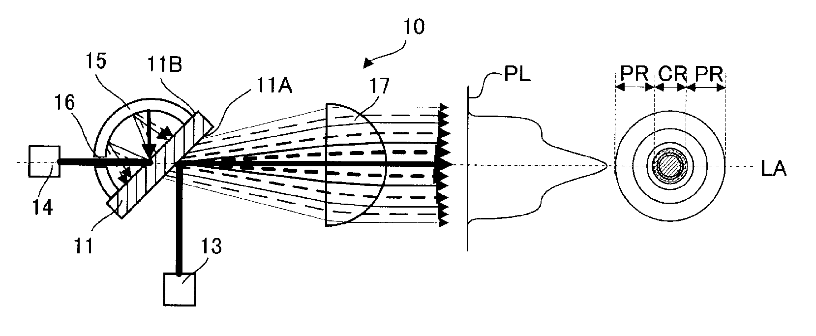
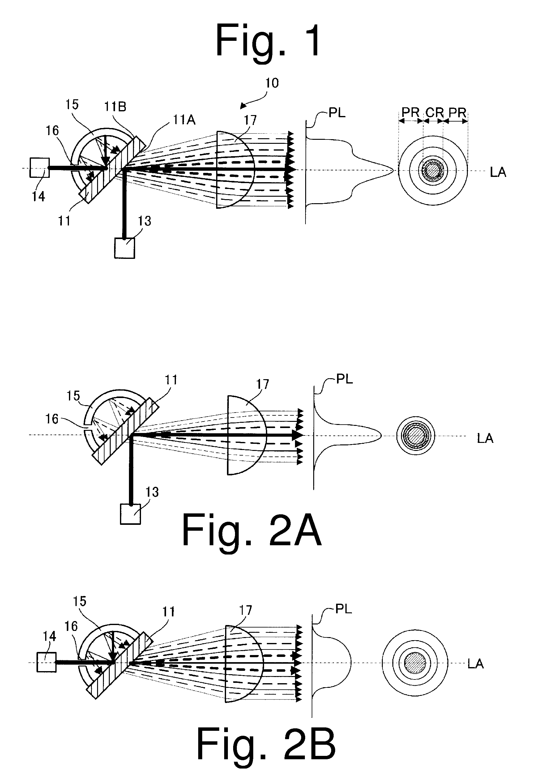
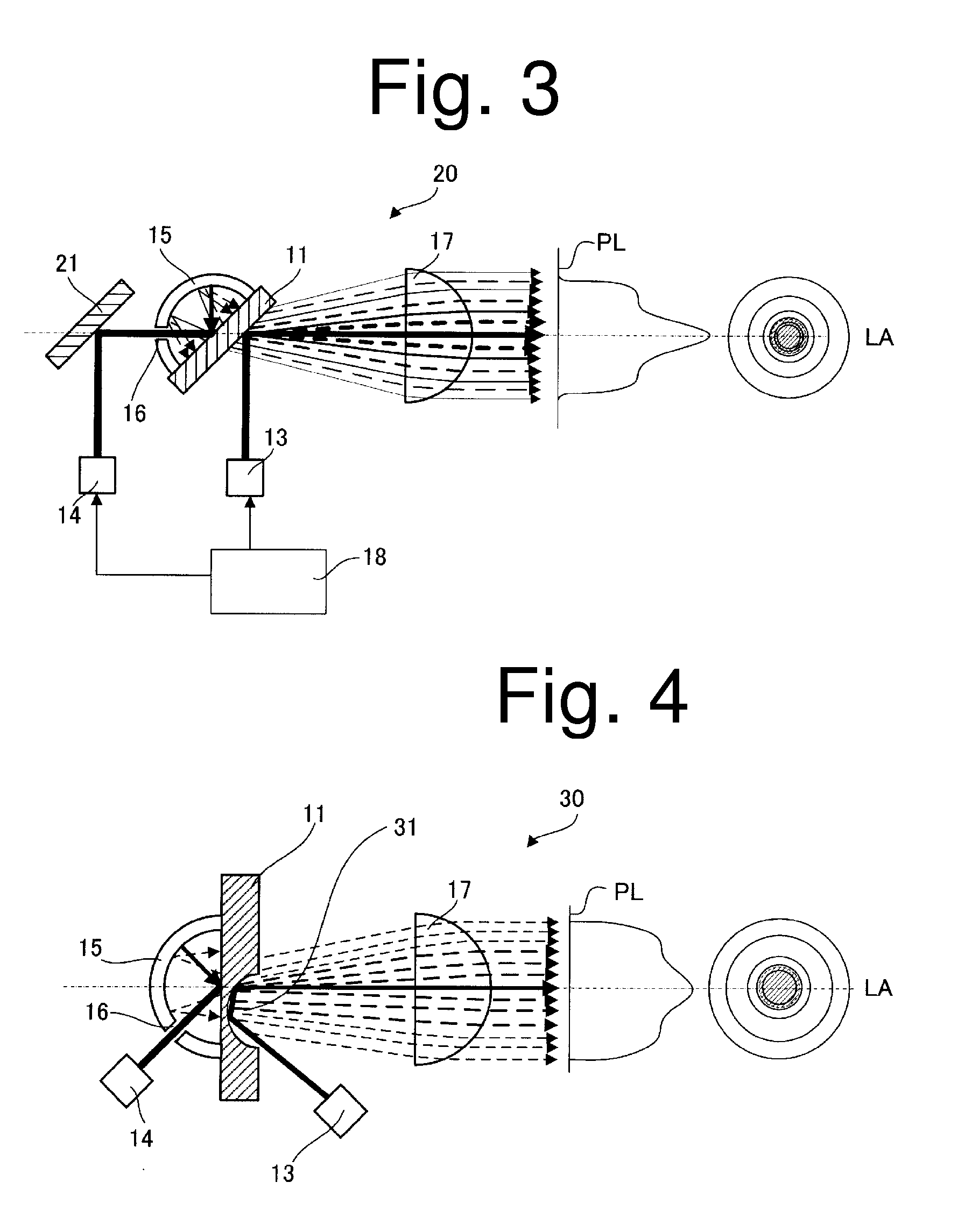
[0031]FIG. 1 is a cross-sectional view illustrating a light-emitting device 10 of a first exemplary embodiment made in accordance with principles of the presently disclosed subject matter when taken along a plane perpendicular to the light irradiation plane PL. Light paths within the light-emitting device 10 are shown in FIG. 1, and the excitation light component is shown by a solid line while the fluorescent light component is shown by a dashed line. The thickness of the line schematically represents the light intensity. The optical axis of the light-emitting device 10 is represented by LA. In the drawings, on the right side of the cross-sectional view, ...


PUM


Abstract

A light-emitting device can include a fluorescent plate having a first surface and a second surface opposite to the first surface and configured to emit fluorescent light by laser irradiation. A first laser light source can be disposed such that the first surface of the fluorescent plate is irradiated with first laser light. A second laser light source can be disposed such that the second surface of the fluorescent plate is irradiated with second laser light. A reflector can include a light passing hole through which the second laser light can pass and can include a concave reflecting surface configured to cover an irradiation region with the second laser light at least on the fluorescent plate. A lens can be disposed in a space closer to the first surface of the fluorescent plate.

Description

[0001]This application claims the priority benefit under 35 U.S.C. §119 of Japanese Patent Application No. 2011-060129 filed on Mar. 18, 2011, which is hereby incorporated in its entirety by reference.TECHNICAL FIELD[0002]The presently disclosed subject matter relates to a light-emitting device, and in particular, to a light-emitting device for use in a vehicle headlamp utilizing a semiconductor laser diode element.BACKGROUND ART[0003]Recent light-emitting devices utilizing a semiconductor laser diode (LD) element can provide white light by using a wavelength conversion material such as a fluorescent material that can be excited by, for example, blue light emitted from the LED element to emit yellow light. Specifically, white light can be obtained by mixing the yellow fluorescent light generated from the fluorescent material due to excitation with the blue excitation light originally emitted from the LD element. Favorable white light can be produced by efficiently exciting the fluor...

Claims


Application Information

Patent Timeline
Patent Type & Authority Applications(United States)
IPC IPC(8): F21V13/14F21V9/40
CPCF21S48/1159F21S48/1154F21S41/147F21S41/16F21S41/148F21S41/176
Inventor HARADA, MITSUNORI
Owner STANLEY ELECTRIC CO LTD
Learn More