
Method and apparatus to perform hydrogen-deuterium exchange

a technology of hydrogen-deuterium exchange and method, which is applied in the field of hydrogen-deuterium exchange, can solve the problems of insufficient dilution of samples in deuterated solvent, added errors in reaction, and meticulous handling of samples, so as to increase the probability of a chemical compound being identified and the effect of improving the determining power

Active Publication Date: 2012-09-13
BIOMOTIF
View PDF14 Cites 12 Cited by
  • Summary
  • Abstract
  • Description
  • Claims
  • Application Information

AI Technical Summary

Benefits of technology

[0024]The sample dividing member divides the sample into a first and a second part, so that the same sample may simultaneously be analysed twice and with different methods of analysis. Hence more information may become available for characterizing and / or quantifying the constituents in the sample. Also less time is needed for the analysis since both detectors may be run in parallel. Preferably the sample divider is arranged to divide the sample into two parts having nearly identical compositions and / or chemical proportions. Preferably the sample dividing member is arranged to divide the chemical sample so that the compositional ratios of the first and the second sample parts are identical to within 15%. Hence it is ensured that the two methods of analysis are made on similar samples, increasing the quality of the information obtained from the two analyses. Otherwise, it may be difficult or impossible to compare the results from the two detectors. Furthermore, the sample dividing member allows for a better control and less variation of the dividing ratios for a series of consecutive samples. By including a sample dividing member after the sample receiver, the sample is divided automatically by the device. The time for performing an experiment may then also decrease in relation to performing the two methods one after the other or on two different devices. The sample dividing member may therefore bring cost savings in for example labour costs. The sample dividing member may also divide a sample into more than two parts, such as three, four or more parts, alternatively, the device may comprise two or more sample dividing members.
[0046]According to one embodiment the computer program product is further adapted to induce the computer to perform the steps receiving a first set of measurement data from the first detector, the data comprising information acquired from measurements on molecules of the at least one compound to be analysed which were ionized by a first ionizer so that the ionized molecules remained intact, and receiving a second set of measurement data from the second detector, the data comprising information acquired from measurements on molecules of the at least one compound to be analysed which were ionized by a second ionizer so that the ionized molecules were fragmented. Thus the computer receives information on both the molecular weight of the intact molecule of the compound to be analysed and of its fragments. Preferably the computer program product is further adapted to induce the computer to perform the steps: fitting the first set of measurement data with information in a first database comprising a library with previously stored measurement values on intact molecules, fitting the second set of measurement data with information in a second database comprising a library with previously stored measurement values on molecular fragments, and combining the results from the first and second fits to increase the determining power when discerning the identity of the at least one compound to be analysed within the chemical sample. Thus the probability of a successful identification of a chemical compound may increase considerably.

Problems solved by technology

The main disadvantage of this approach is the necessary dilution of the sample in the deuterated solvent, since about 90 percent of total volume of reacting solution should correspond to the deuterated solvent.
The later is an important problem, since the necessary dilution forces the user to utilize a high amount of sample for each analysis.2. In-tube mixing of target molecule with deuterated solvent followed by reverse-phase liquid chromatography.
The laborious and meticulous nature of the sample-handling (in order to avoid back exchange) is the mayor drawback of this approach.
Besides the labor-intensive characteristics of this technique, each step can potentially add errors to the reaction (e.g. lack of reproducibility in the collection-timing, acidification and froze / defrost procedures).3. In-tube mixing of target molecule with deuterated solvent followed by pepsin digestion and reverse-phase liquid chromatography.
Briefly, labor-intensive and potentially prompt to errors due to the many sample-handling steps (e.g. lack of reproducibility in the collection-timing, acidification and froze / defrost procedures).
Now, since most of target molecules are dissolved in aqueous buffers (or pure water), the necessary dilution of the sample in the deuterated solvent—normally using dilution factors between 4 to 10 times—is detrimental for the overall sensitivity of the technique, requiring the use of a higher amount of sample per experiment.
For certain molecules however, there may be problems in that the fragment distributions may be very similar, so that it is almost impossible to guess at its identity.
The necessary modification of the target molecule (or ligand) and the blockade of the structure of the target molecule (or ligand) involved in linking it to the solid surface are the main problems of these technologies.
Also, the hiding or blocking of the molecular structures of the target molecule (or ligand) that are associated with the linkage onto the solid support has the potential to interfere with the normal interaction of the target molecule with the ligand.
A challenge to the pharmaceutical industry is how to analyze such libraries comprising a vast number of compounds.

Method used


Image

  • Method and apparatus to perform hydrogen-deuterium exchange
  • Method and apparatus to perform hydrogen-deuterium exchange
  • Method and apparatus to perform hydrogen-deuterium exchange

Examples


Embodiment Construction

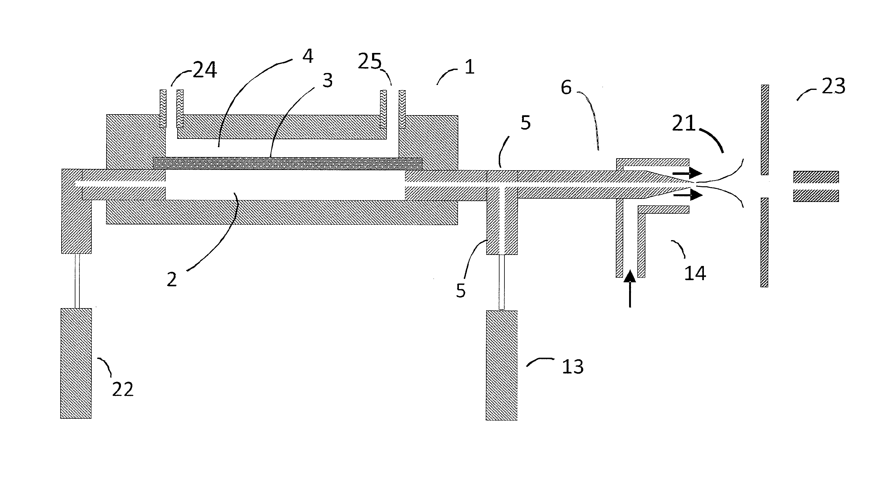
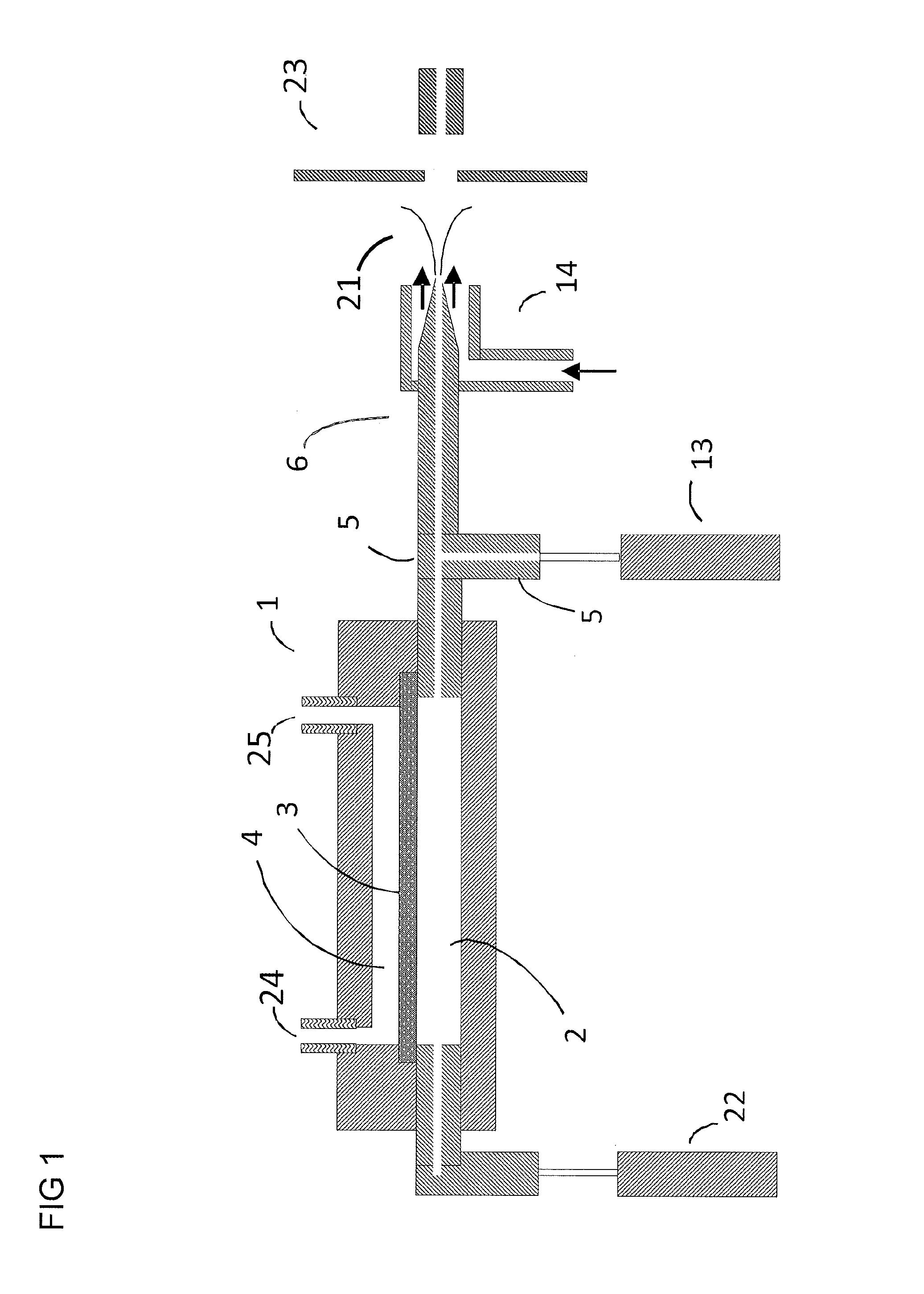
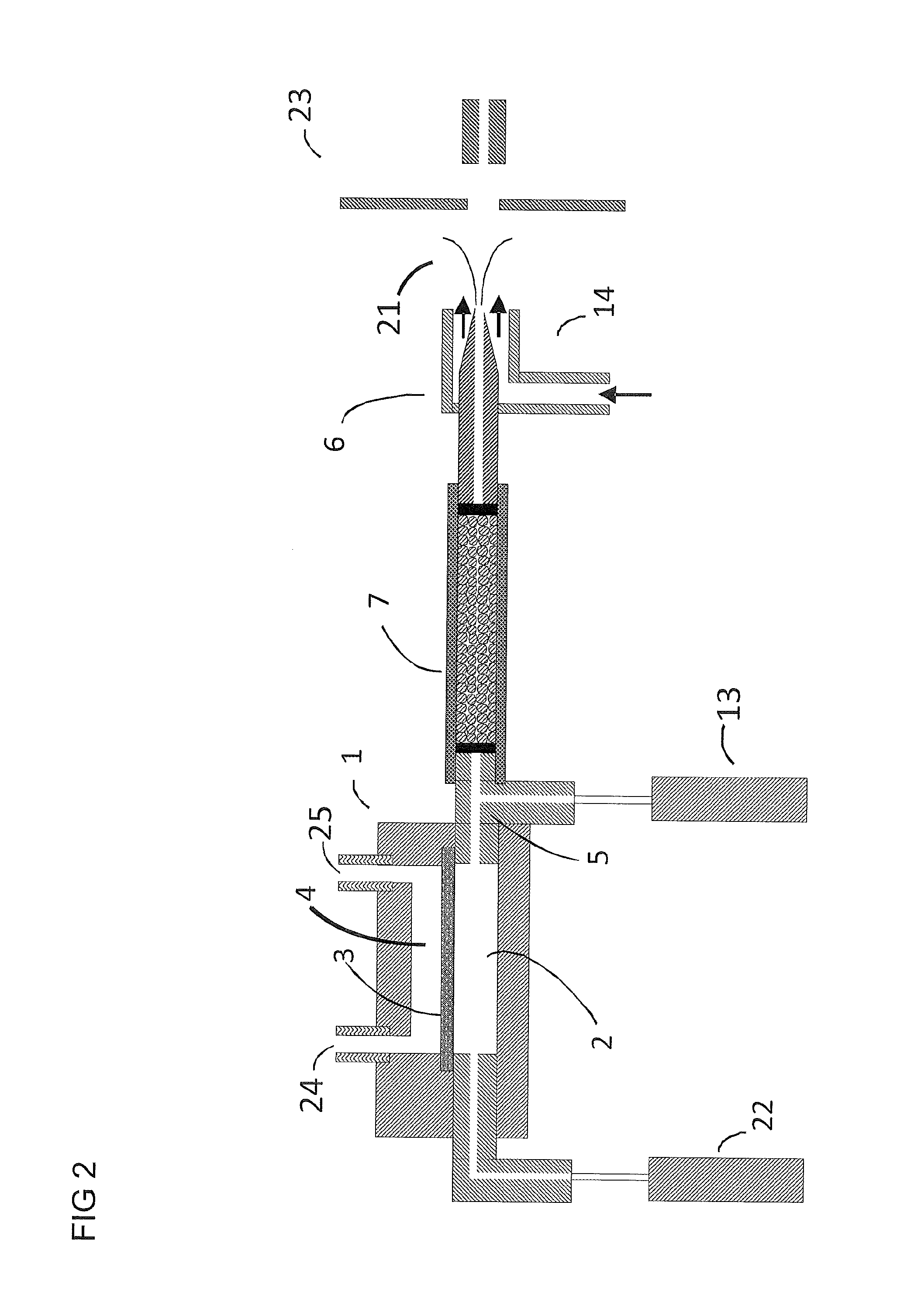
[0068]I. Electrospray ionization produces charged droplet using spray devices utilizing unassisted Electrospray or pneumatic nebulization. Unassisted Electrospray requires the formation of a stable Taylor cone jet from the sample solution exiting a channel or tube in the presence of an electric field. Depending on the sample composition, it may not be possible to form a stable Taylor cone at atmospheric pressure (e.g. high conductivity, high surface tension, and high flow rate). In order to solve these limitations, ultrasonic and pneumatic nebulization charged droplet sprayer devices have been developed. Both nebulization techniques can be used in the embodiments described below. Pneumatic nebulization sprayer devices are most widely used for the generation of charged liquid droplets from sample solutions. Pneumatic nebulization produces charged droplets from channels or tube tips in the presence of an electric field by pneumatically shearing the solution as it exits the tube. The g...


PUM

PropertyMeasurementUnit
pHaaaaaaaaaa
timeaaaaaaaaaa
timeaaaaaaaaaa

Abstract

Apparatus and methods to perform hydrogen / deuterium exchange using semipermeable membranes are described. The system has two channels separated by a semipermeable membrane. One channel comprises a flow carrying the analyte of interest, and the second channel comprises a solution comprising a deuterated solvent (e.g. deuterium oxide). The system does not require an external electric field gradient across the membrane to perform the hydrogen-deuterium exchange procedure. The present invention facilitates sample and reagent handling as well as simplifies manufacture of devices and / or instrumentation related to deuterium exchange.Further described is a chemical analysation device for analysing chemical compositions and / or compounds, and a method for analysing chemical compounds and a computer program product for inducing a computer to perform steps in the method. Also described is a method for analyzing interactions between analytes and charged molecules, and calculating binding coefficients of the analytes with respect to the charged molecules.

Description

FIELD OF INVENTION[0001]This invention relates to the field of hydrogen / deuterium exchange in which an analyte comprising one or more exchangeable hydrogen(s) in its structure, it is exchanged into a deuteron by means of subjecting the analyte of interest to a deuterated solvent (e.g. deuterium oxide). The velocity and / or localization of the exchange can give structural and / or interactional and / or binding information about the analyte of interest.[0002]The present invention further relates to a chemical analysation device, a method of chemical analysation, and a computer program product for chemical analysation.[0003]The present invention further relates to a method for analyzing molecular interactions.BACKGROUND[0004]I. Some molecules have hydrogen atoms bound to their structure which—under some conditions—are continuously exchanged with hydrogen atoms present in the surrounding solvent (e.g. water). A typical example of this phenomenon is the hydrogen present at the amide group in...

Claims


Application Information

Patent Timeline
Patent Type & Authority Applications(United States)
IPC IPC(8): G01N27/72G01N31/00C12M1/34
CPCG01N30/7266H01J49/00C07K1/13Y10T436/24G01N2030/067G06F19/703G01N30/06B01D15/361G01N27/26G01N30/00G01N30/96G01N2001/4011G01N2001/4016G01N2030/146G16C20/20H01J49/0018H01J49/04H01J49/0431H01J49/165
Inventor LAVOLD, THORLEIFASTORGA WELLS, JUAN
Owner BIOMOTIF
Learn More