
Filter arrangement

a filter and filter technology, applied in the field of filter arrangement, can solve the problems that the properties of these off-the-shelf filters may not always meet the design criteria, and achieve the effect of improving the transmit signal

Active Publication Date: 2012-09-13
KATHREIN SE
View PDF9 Cites 67 Cited by
  • Summary
  • Abstract
  • Description
  • Claims
  • Application Information

AI Technical Summary

Benefits of technology

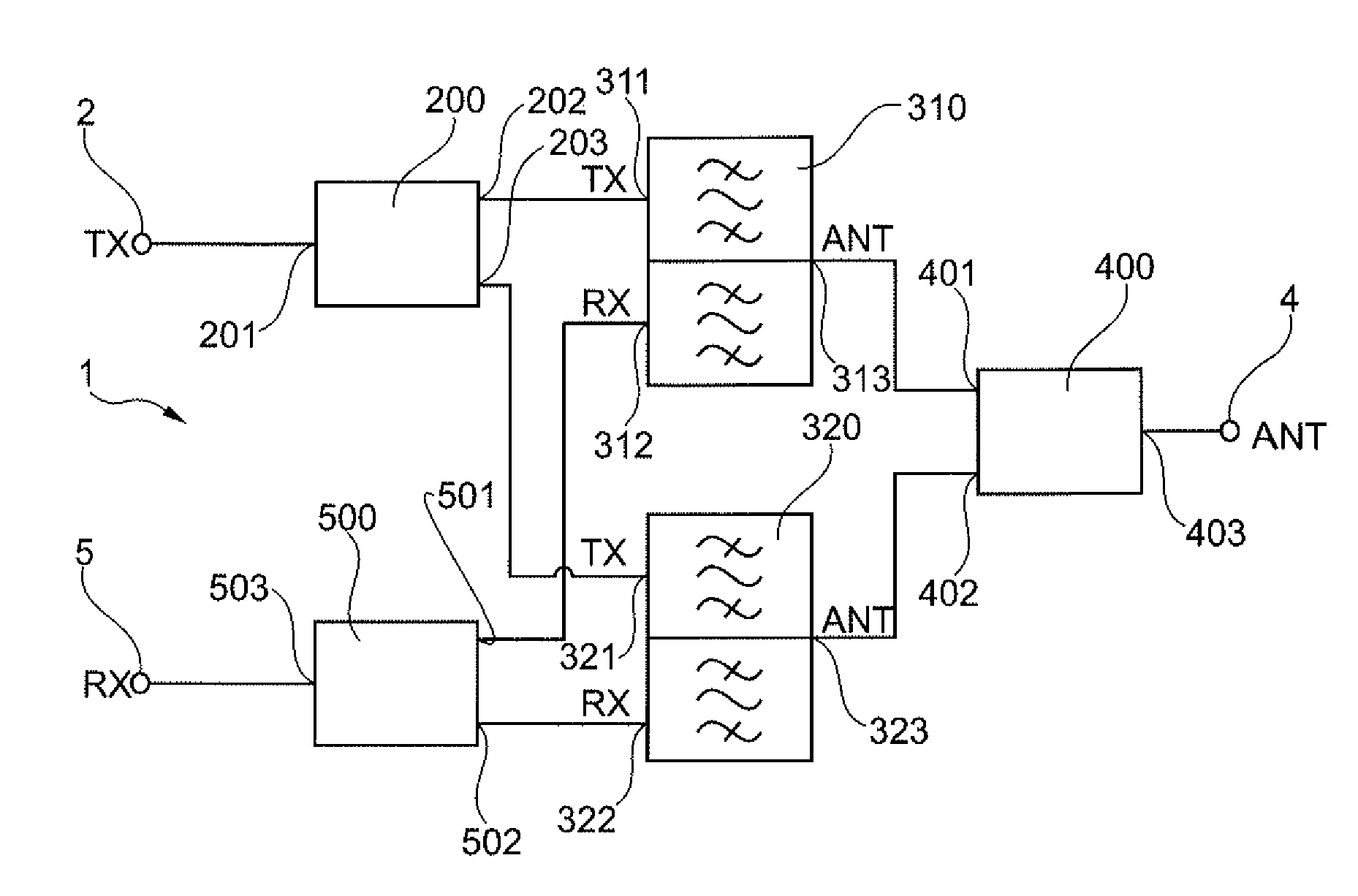
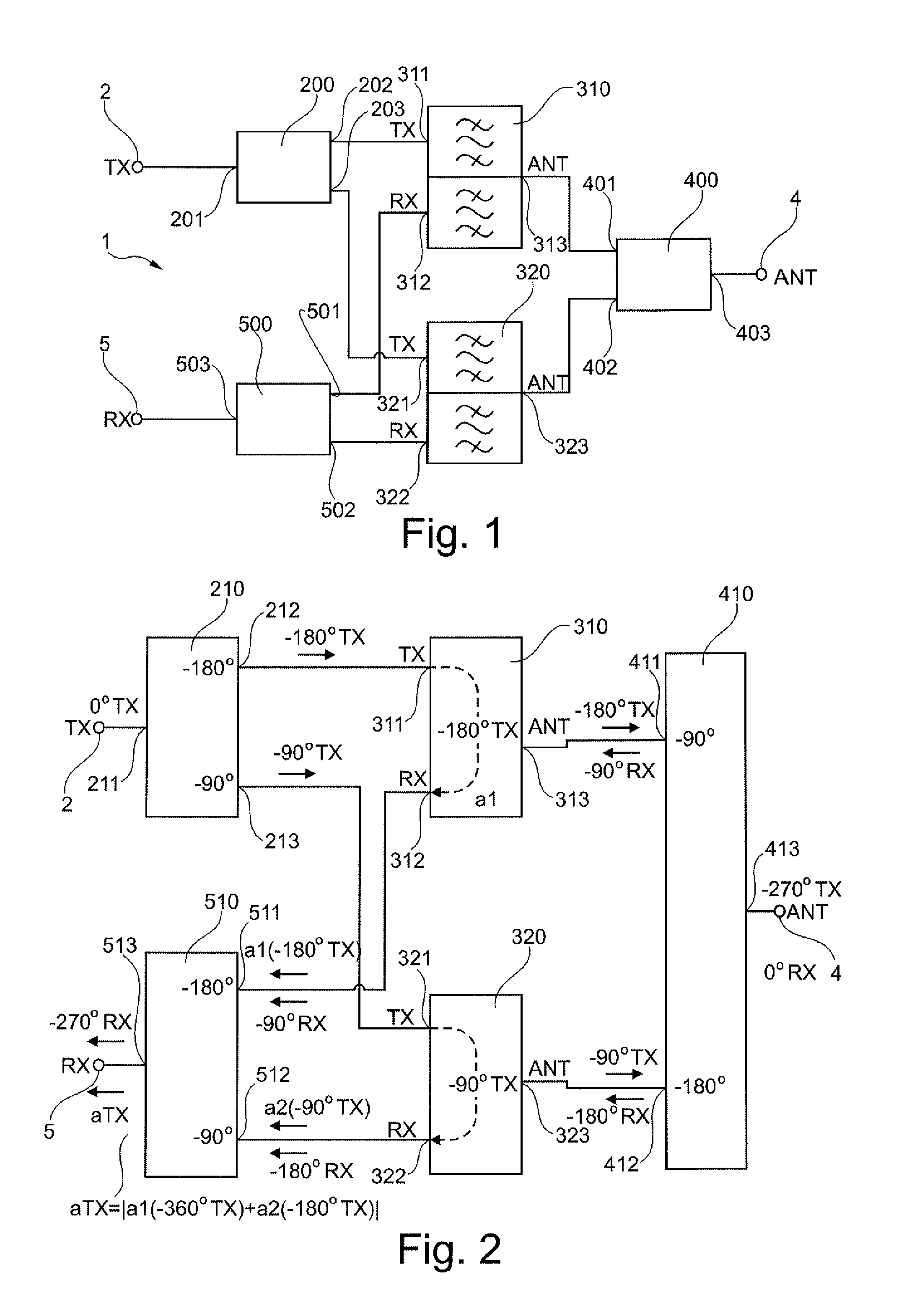
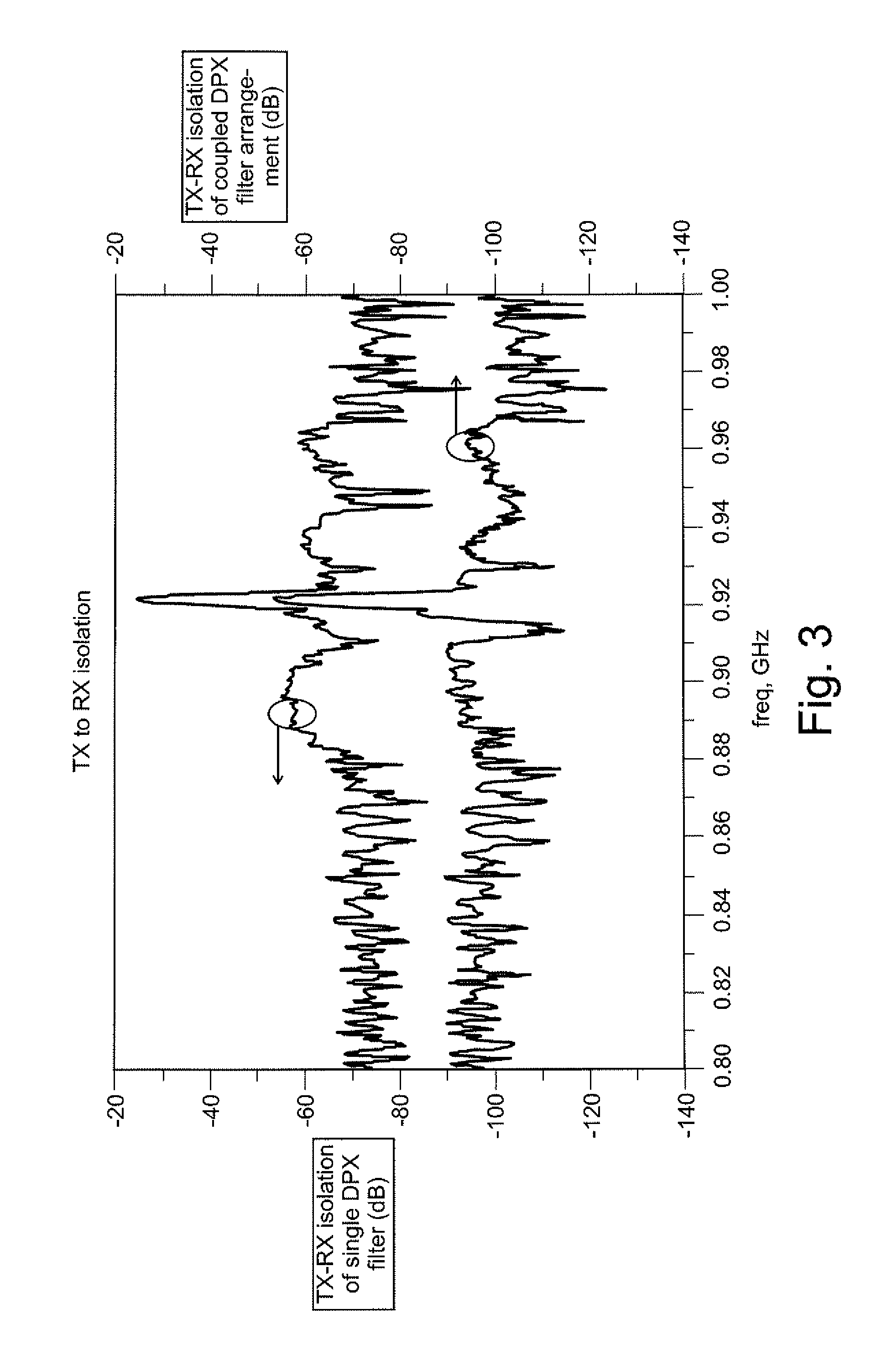
[0005]It is an aspect of the teachings of the present disclosure to provide a filter arrangement for filtering a radio transmit signal and radio receive signal, comprising a first duplex filter, the first duplex filter comprising a first transmitter port, a first receiver port, and a first antenna port, and further comprising a second duplex filter, the second duplex filter comprising a second transmitter port, a second receiver port, and a second antenna port. The filter arrangement further comprises a signal divider for splitting a transmit input signal into a first transmitter signal portion and a second transmitter signal portion, the first transmitter signal portion being passed to the first transmit port of the first duplex filter, and the second transmitter signal portion being passed to the second transmitter port of the second duplex filter. The filter arrangement further comprises a signal combiner / divider with a first signal / combiner port, connected to the first antenna port of the first duplex filter, and a second signal / combiner port, connected to the second antenna port of the second duplex-filter, the signal combiner / divider combining a first filtered transmit portion signal and a second filtered transmit portion signal into a single filtered transmit signal, which is provided at a third signal / combiner port of the signal combiner / divider, and for splitting the radio receive signal received at the third combiner / divider port into a first receive signal portion and a second receive signal portion, the first receive signal portion being provided at the first signal combiner / divider port and the second signal portion being provided at the second signal combiner / divider port. The filter arrangement further comprises a signal combiner with a first signal combiner input, connected to the first receive port of the first duplex filter, and with a second signal combiner port of the second duplex filter, connected to the second receive port of the second duplex filter, the signal combiner combining a first filtered receive signal portion and a second filtered receive signal portion into a single filtered receive signal, which is provided at a third output of the signal combiner. This filter arrangement enables the improvement of the transmit signal to receive signal isolation compared to a single duplex filter.
[0011]Another aspect of the teaching of the present disclosure is that the transmit signal splitter is incorporated in the compensation controller and the first transmit signal portion is derived from the transmitter signal by electronically applying a 180° phase delay to the transmitter signal and the second transmitter signal portion is derived from the transmitter signal by electronically applying a 90° phase delay to the transmitter signal. The electronically generated phase shift of the first transmitter signal portion and the second transmitter signal portion are provided in order to compensate the phase shift that will be applied by the signal divider / combiner to the first transmitter signal portion and the second transmitter signal portion. As the compensation controller has to adopt the gain / phase of the first transmitter signal portion and the second transmitter signal portion it can be used at the same time to generate the phase delay of the first transmitter portion signal and the second transmitter portion signal so that a signal splitter becomes obsolete. As the generation of electronically phase-delayed signals does not need any extra space on the circuit board, the advantage of this arrangement is that it saves the space of the obsolete signal splitter on the circuit board.

Problems solved by technology

However, the technical properties of these off-the-shelf filters may not always meet the design criteria a circuit designer has in mind when designing a radio station.

Method used


Image

  • Filter arrangement
  • Filter arrangement
  • Filter arrangement

Examples


Embodiment Construction

[0021]The invention will now be described on the basis of the drawings. It will be understood that the embodiments and aspects of the invention described herein are only examples and do not limit the protective scope of the claims in any way. The invention is defined by the claims and their equivalents. It will be understood that features of one aspect or embodiment of the invention can be combined with a feature of a different aspect or aspects and / or embodiments of the invention.

[0022]FIG. 1 shows as an aspect of the present disclosure a duplex filter arrangement 1 for filtering a transmit signal TX which is received at a filter arrangement transmit input 2 and providing the filtered transmit signal at an antenna terminal 4. A receive signal RX, which is received at the antenna terminal 4, is filtered and the filtered receive signal is provided at a filter arrangement receive output 5. A plurality of the transmit signals TX together form a transmit band. A plurality of the receive...


PUM


Abstract

A filter arrangement for filtering a radio transmit signal and radio receive signal, comprising a first duplex filter and a second duplex filter, a signal divider for splitting a transmit input signal into a first transmitter signal portion and a second transmitter signal portion, the first transmitter signal portion being passed to the a transmit port of the first duplex-filter, and a second signal portion being passed to the second transmitter port of the second duplex filter. The filter arrangement further comprising a signal combiner / divider for combining a first filtered transmit portion signal and a second filtered transmit portion signal into a single filtered transmit signal. The filter arrangement further comprising a signal combiner for combining a first filtered receive signal portion and a second filtered receive signal portion into a single filtered receive signal, which is provided at a third output of the signal combiner. With such a filter arrangement the suppression of noise from the transmit signal in the receive signal is improved.

Description

FIELD OF THE INVENTION[0001]The field of the present application relates in general to a filter arrangement and in particular to a radio station with a filter arrangement. The field of the application also relates to a method of manufacturing a filter arrangement.BACKGROUND OF THE INVENTION[0002]Filters are designed, for example, for a specific frequency band. Signals within that specific frequency band will pass through the filter from a first port to a second port whereas signals outside of the specific frequency band will be prevented from passing through the filter. The filters may be produced as a combination of resistors, inductors, and capacitors or as ceramic filters, such as but no limited to surface acoustic wave filters or film bulk acoustic resonators. Dependent on their technology each filter may be distinguishable from other filters by electrical characteristics such as insertion loss, out-band signal rejection, electric power durability, as well as in size and price.[...

Claims


Application Information

Patent Timeline
IPC IPC(8): H04B7/00
CPCH04B1/52H01P5/12H04B1/50H03H7/463H03H9/703H01P5/16
Inventor WEISS, HOLGER
Owner KATHREIN SE
Learn More