
Apparatus and method for controlling transportation of tape medium

Active Publication Date: 2012-09-13
IBM CORP
View PDF0 Cites 12 Cited by
  • Summary
  • Abstract
  • Description
  • Claims
  • Application Information

AI Technical Summary

Benefits of technology

[0012]Described embodiments enhance performance in writing without preventing achievement of a target read data rate by providing an apparatus of controlling transportation of a tape medium during data writing to the tape medium, comprising a determination unit that determines a speed for transporting the tape medium in a way that a portion of the tape medium transported without data writing due to skipping of backhitch has a length not preventing achievement of a target read data rate in reading written data from the tape medium.
[0018]Furthermore, the described embodiments may also provide a method of controlling transportation of a tape medium during data writing to the tape medium, the method including the steps of: acquiring a target read data rate in reading written data from the tape medium; and determining a speed for transporting the tape medium in a way that a portion of the tape medium transported without data writing due to skipping of backhitch has a length not preventing achievement of the target read data rate in reading written data from the tape medium.
[0020]The described embodiments provide high performance without preventing achievement of a target read data rate.

Problems solved by technology

Since the writing of next data starts after completion of this backhitch, frequent reception of synchronization commands leads to considerable reduction in writing performance.
The use of the high tape speed leads to an increase in the idly-transported length, and thereby causes a problem of lowering the performance in reading.
Therefore, a time of entire write processing cannot be reduced in consideration of an occurrence frequency of backhitch and a time required for backhitch.

Method used


Image

  • Apparatus and method for controlling transportation of tape medium
  • Apparatus and method for controlling transportation of tape medium
  • Apparatus and method for controlling transportation of tape medium

Examples


Embodiment Construction

[0028]Hereinafter, embodiments of the present invention will be described in details with reference to the accompanying drawings.

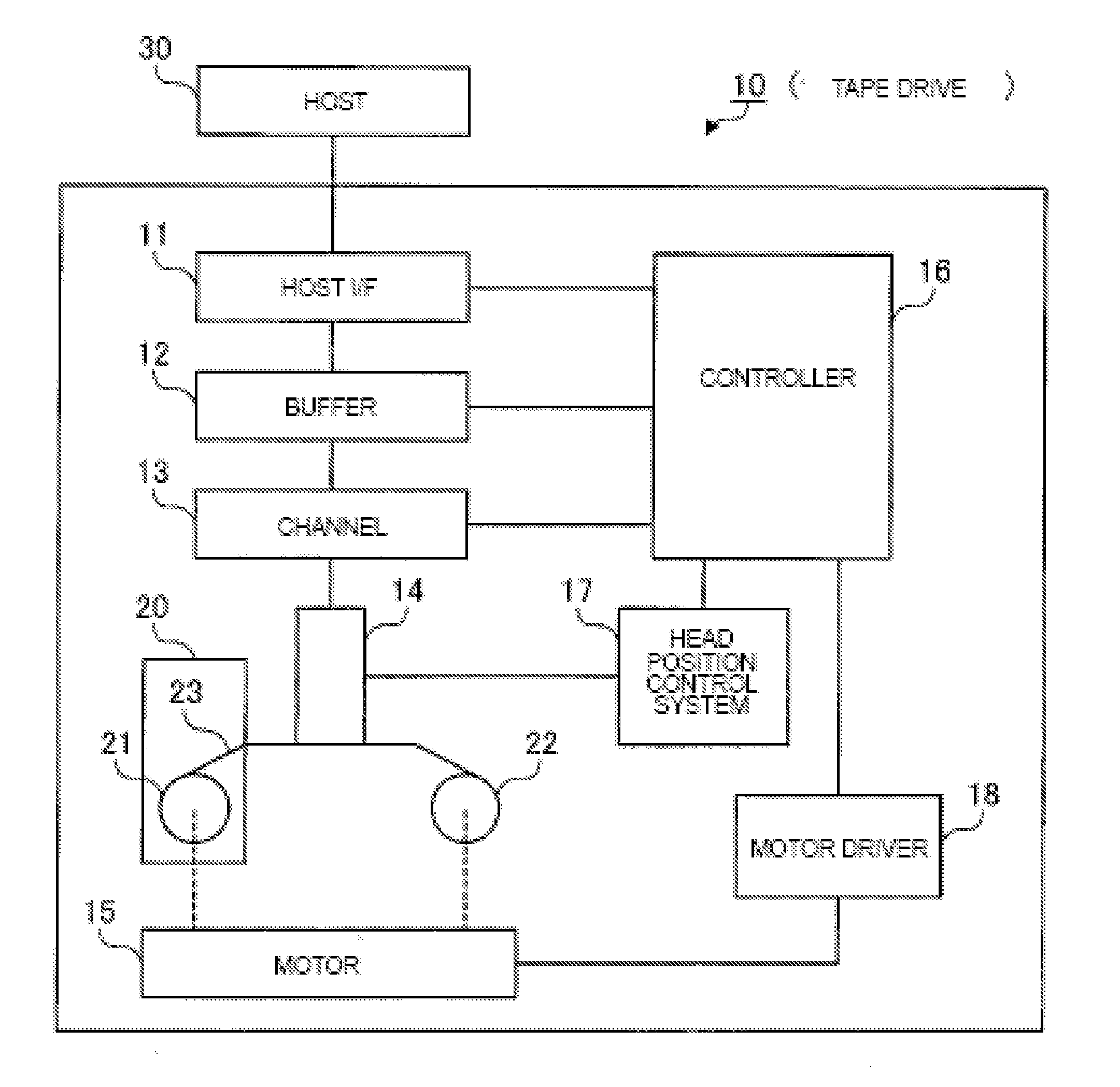
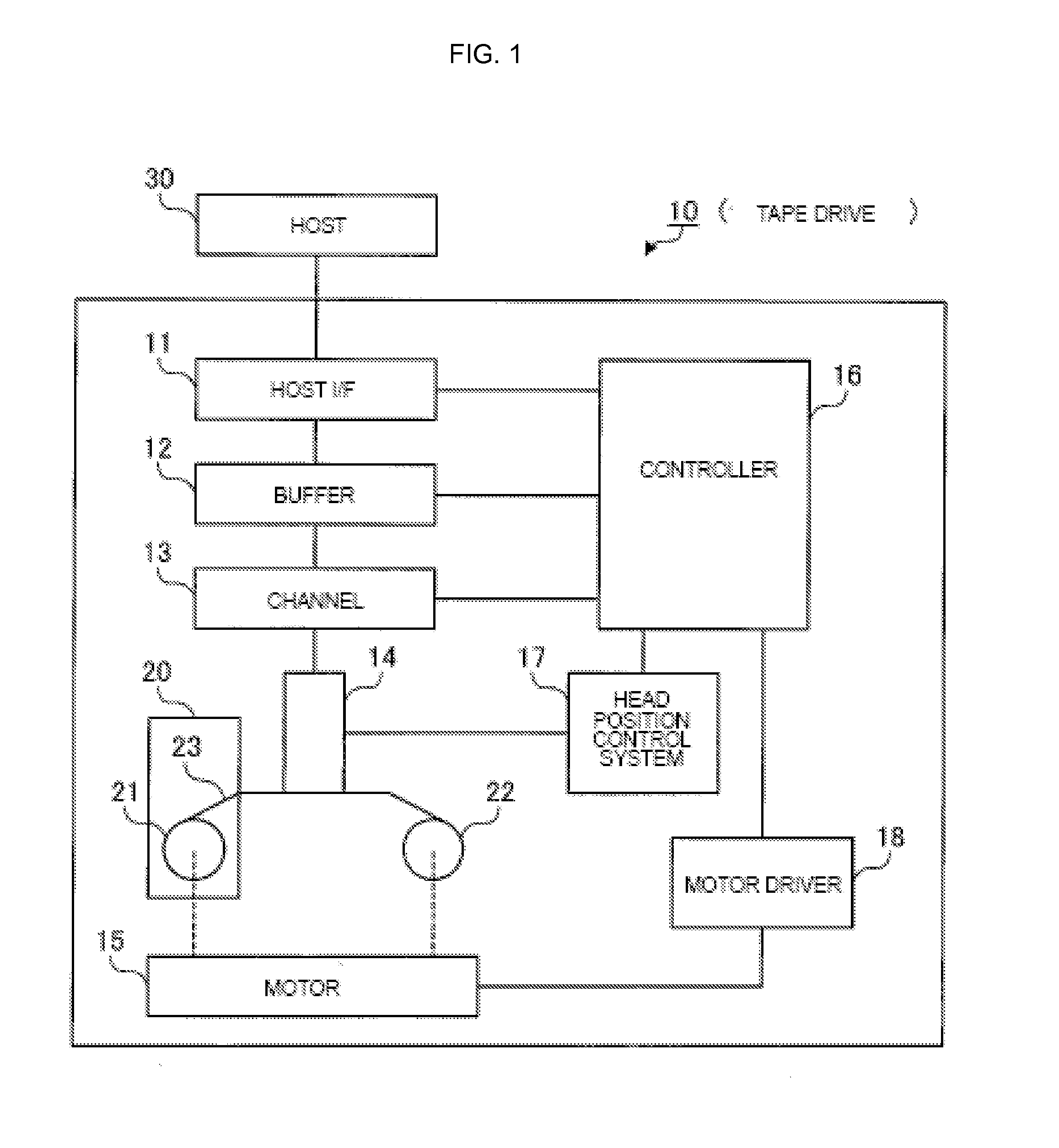
[0029]FIG. 1 is a diagram illustrating a configuration example of a tape drive 10 to which an embodiment of the present invention is applied. This tape drive 10 includes a host interface (hereinafter, referred to as “host I / F”) 11, a buffer 12, a channel 13, a head 14, and a motor 15. In addition, the tape drive 10 includes a controller 16, a head position control system 17, and a motor driver 18. Moreover, FIG. 1 also illustrates a tape cartridge 20, because the tape cartridge 20 is mountable in the tape drive 10 by being inserted thereinto. This tape cartridge 20 includes a tape 23 wound around reels 21 and 22. With rotations of the reels 21 and 22, the tape 23 is transported in a longitudinal direction, i.e., in a direction from the reel 21 to the reel 22 or a direction from the reel 22 to the reel 21. Note that, a magnetic tape is illustrated as the ta...


PUM


Abstract

High performance is obtained without preventing achievement of a target read data rate.In a controller 16 of a tape drive, a command processing unit 41 receives a synchronization command, and a buffer management unit 42 passes data in a buffer to a channel input-output unit 43. Then, upon completion of writing the data to the tape, a backhitch determination unit 44 determines whether or not to execute backhitch. If it is determined that backhitch should be skipped, the speed determination unit 46 determines a tape speed that minimizes a sum of a time required to write data without backhitch within a range where a data amount of a monitor target is to be written in order to achieve a target read data rate, and a time required to write data with backhitch within the range. Then, an operation signal output unit 49 issues an instruction to change the tape speed to the determined tape speed after execution of backhitch.

Description

BACKGROUND OF THE INVENTION[0001]1. Field of the Invention[0002]The present invention relates to an apparatus and a method for controlling transportation of a tape medium. In particular, the present invention relates to an apparatus and a method for controlling transportation of a tape medium during data writing to the tape medium.[0003]2. Description of the Related Art[0004]During data writing, some tape drives write data to tape media, such as magnetic tapes, in conformity with LTO (Linear Tape Open), for example, by receiving synchronization commands from a host (an application program) at regular or sporadic time intervals. The synchronization command is a command to forcedly write data accumulated in a buffer in a tape drive to a tape medium. Such regular reception of synchronization commands assures an application program that all data sent to the tape drive by the application program itself is already written to the tape medium and is not left any more in the buffer in the ta...

Claims


Application Information

Patent Timeline
IPC IPC(8): G11B15/46G11B5/008
CPCG11B15/20G11B15/26G11B20/10009G11B2220/90G11B27/36G11B2020/10759G11B20/10527G11B15/442G11B15/444G11B5/00813G06F3/0613G06F3/0656G06F3/0682
Inventor KATAGIRI, TAKASHIMORI, YUHKOOISHI, YUTAKA
Owner IBM CORP
Learn More