
Electrically actuated valve for control of instantaneous pressure drop and cyclic durations of flow

a technology of electric actuator and instantaneous pressure drop, which is applied in the direction of valve operating means/release devices, machines/engines, water supply installation, etc., can solve the problems of large changes in pressure, high cost of spraying components, and low margin of agricultural spraying, so as to improve germination and early plant development

Active Publication Date: 2012-09-13
CAPSTAN
View PDF8 Cites 88 Cited by
  • Summary
  • Abstract
  • Description
  • Claims
  • Application Information

AI Technical Summary

Benefits of technology

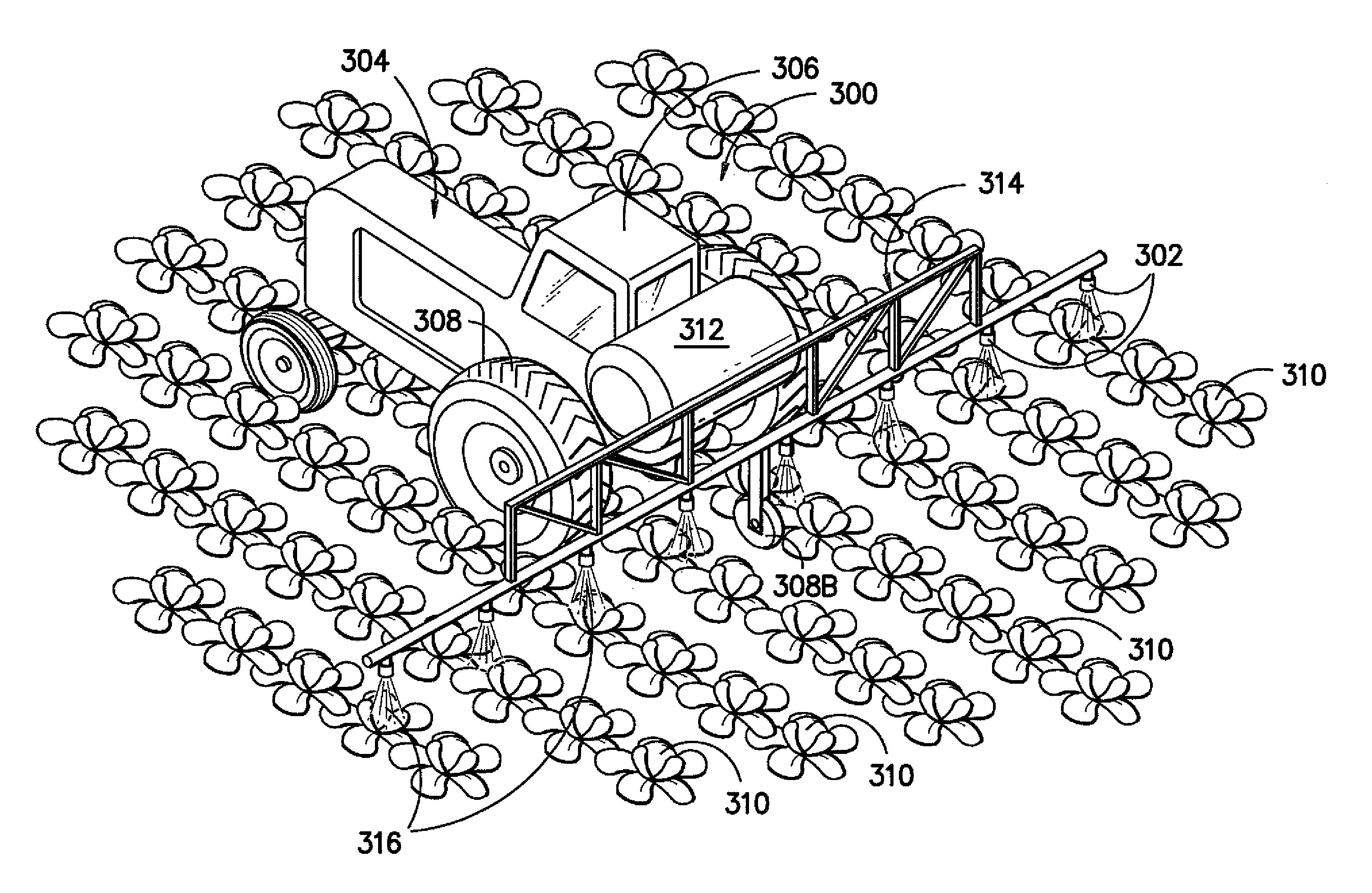
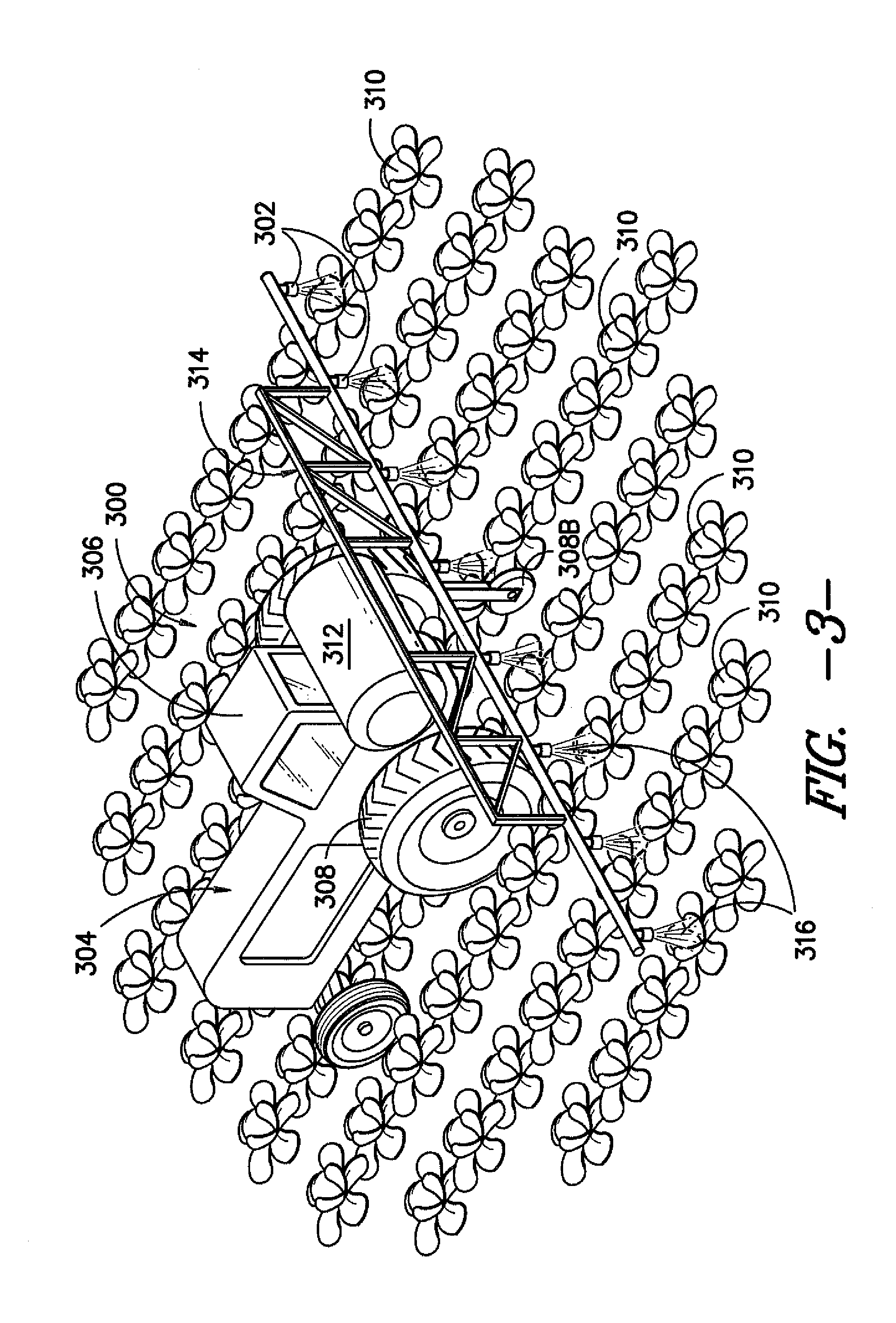
[0032]Also in this aspect of the present subject matter, the nozzle assembly may be configured to throttle fluid flow based on the position of the poppet wherein the duration of the pulse of the valve controls the placement of chemical in a planting application. For example, fertilizers and pesticides may be sprayed directly on or adjacent to seed, seedling or other plant precursor placements to enhance germination and early plant development.
[0033]In this aspect of the present subject matter, the nozzle assembly may be configured to throttle fluid flow based on the position of the poppet wherein the synchronization and duration of the pulse of the valve controls the placement of chemical on or between plants in a row crop application. For example, the control of fluid flow may regulate the application rate of the chemical.
[0034]Also in this aspect of the present subject matter, the nozzle assembly may be configured to throttle fluid pressure based on the position of the poppet wherein the synchronization and duration of the pulse of the valve controls the placement of chemical on or between plants in a row crop application. For example, the control of fluid pressure may regulate the distribution of droplet size of the chemical.
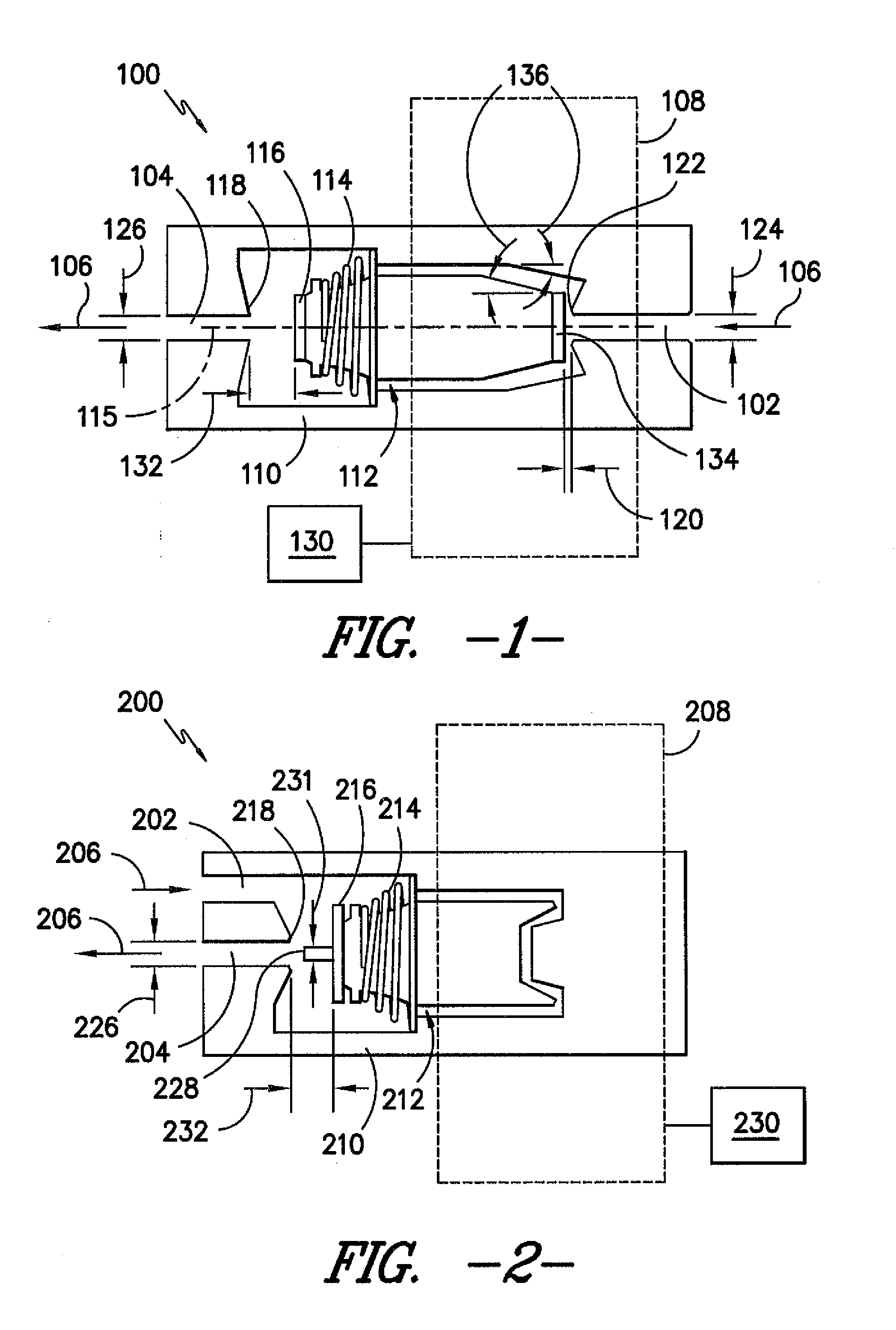
[0048]In this aspect of the present subject matter, the method may allow for the simultaneous control of instantaneous pressure drop across and the duration of cyclic flow pulses through the valve.

Problems solved by technology

Moreover, agricultural spraying is typically a low-margin business, as the spraying components used are often very expensive.
Consequently, large changes in pressure are required to make moderate flow rate changes.
Often, at low pressures the pattern does not fully develop.
This can result in incomplete coverage or excess coverage in portions of the same field.
A side effect of these increased efficiencies is that very wide spray booms exaggerate application rate errors.
One example of these rate errors exists if the spray boom is executing a turn.
Thus, some areas receive more material than desired resulting in higher chemical residues, crop damage, and wasted pesticide while other areas receive less material and a loss of pest control.
Unfortunately, even with modem PWM flow control systems, droplet size is controlled in per-machine width resolution, that is, every nozzle across the entire boom must produce the same droplet size spectrum.
This application would reduce the efficacy of the application in areas not at risk of drift.
However, one of the primary limitations to precision agricultural technology is the lack of high-quality actuation systems to match the precision of today's advanced sensing systems.
In addition, the spray actuator exhibited a lack of linearity of control.
While various implementations of spray nozzles, nozzle assemblies, spraying systems and control systems have been developed, no design has emerged that is known to generally encompass all of the desired characteristics hereafter presented in accordance with aspects of the present subject matter.

Method used


Image

  • Electrically actuated valve for control of instantaneous pressure drop and cyclic durations of flow
  • Electrically actuated valve for control of instantaneous pressure drop and cyclic durations of flow
  • Electrically actuated valve for control of instantaneous pressure drop and cyclic durations of flow

Examples


Embodiment Construction

[0070]Reference now will be made in detail to embodiments of the invention, one or more examples of which are illustrated in the drawings. Each example is provided by way of explanation of the invention, not limitation of the invention. In fact, it will be apparent to those skilled in the art that various modifications and variations can be made in the present invention without departing from the scope or spirit of the invention. For instance, features illustrated or described as part of one embodiment can be used with another embodiment to yield a still further embodiment. Thus, it is intended that the present invention covers such modifications and variations as come within the scope of the appended claims and their equivalents.

[0071]In general, the present subject matter is directed to an electric solenoid valve that provides simultaneous control of instantaneous pressure drop across and cyclic durations of fluid flow through the valve. In several embodiments, an actuator or popp...


PUM


Abstract

An electric solenoid valve, methods for operating and / or actuating the solenoid valve, valve system diagnostics, and applications for use are described. The valve may be designed to actuate in a manner so as to control liquid flow into and / or through a device, such as a spray nozzle. By altering the characteristics of the electrical signal transmitted to the solenoid valve, the instantaneous pressure across the valve and duration of fluid flow through the valve can be controlled with a single actuator. Controlled cyclic durations of flow may be implemented to regulate the exact timing of flow through the valve. Alternatively, cyclic durations may occur with a pulse-width modulation technique in which the duty cycle regulates average flow rate through the valve.

Description

CROSS-REFERENCE TO RELATED APPLICATIONS[0001]This application claims priority to previously filed U.S. Provisional Patent Application entitled “Electrically Actuated Valve for Control of Instantaneous Pressure Drop and Average Flowrate,” assigned U.S. Ser. No. 61 / 449,924, filed Mar. 7, 2011 and which is hereby fully incorporated herein by reference in its entirety for all purposes.STATEMENT REGARDING FEDERALLY SPONSORED RESEARCH OR DEVELOPMENT[0002]Certain aspects of the present invention were conceived during research funded by a USDA-CSREES-SBIR-002363 grant. The Government may have certain rights in the present invention.FIELD OF THE INVENTION[0003]The present subject matter relates generally to the design and operation of electrically actuated valves. More particularly, the present subject matter relates to the geometry, controlling methods, diagnostics, and application of an electric solenoid valve which may be configured to simultaneously control the instantaneous pressure dro...

Claims


Application Information

Patent Timeline
Patent Type & Authority Applications(United States)
IPC IPC(8): A01M7/00A01G25/16B05B12/06B05B1/08F16K31/06F01L3/10
CPCA01G25/16B05B15/02B05B12/085B05B12/004B05B12/008B05B15/50B05B1/083B05B1/3053Y10T137/0318Y10T137/86413F16K31/0606F16K31/0658F16K31/0627B05B12/087
Inventor NEEDHAM, DUANEHOLTZ, ANDREW J.
Owner CAPSTAN
Learn More