
Continuous-Wire Transport Conveyor for Food Dehydration

Inactive Publication Date: 2012-09-13
JOHNSON JR NOLTON C
View PDF13 Cites 5 Cited by
  • Summary
  • Abstract
  • Description
  • Claims
  • Application Information

AI Technical Summary

Benefits of technology

[0018]Instead, the moving conveyor surface of the disclosed device maximizes space for airflow past supported food or other material, between large parallel gaps between a single wire or cable which is continuously wrapped around grooved supporting rollers to maintain the wire in parallel strands abutting large air gaps. Movement of the surface is simple and provided by two rotating drums.
[0031]It is a further object of the invention to eliminate the collection of food and germs and pathogens found in woven or intertwined belts, by using a single wire which may be continuously cleaned in real time.

Problems solved by technology

Further, removing moisture from food dramatically reduces the weight of the food.
Unfortunately, such conventional conveyors using woven or knitted style mesh tend to collect food parts during the process which causes clogged gaps between the wire mesh forming the moving screen.
This is because of the interwoven threads or yarn, are not easily evenly tensioned since the individual threads forming the weave or mesh do not communicate tension evenly to the side edges and ends of the formed belt.
If the woven or knitted mesh material is stretched too tightly, in an effort to flatten it out under the weight of carried food, it can easily become over taught causing rips to form in the formed belt thereby damaging or destroying it.
As a consequence of the inherent problem with tensioning woven or knitted or otherwise meshed belt materials, and the trade off of over-tensioning versus the potential for damage to the belt, such belts tend to sag under the weight of food placed thereon.
They also sag if the weight of the food thereon is not evenly positioned to evenly distribute the aggregate weight thereof.
Further, because of the constant sagging and uneven tension, over time as the formed mesh of the belt stretches from use.
This causes clogged gaps between the mesh fibers or wires which lessens the airflow through the belt, inhibiting drying of the food.
Further, food collecting in the gaps between woven wires and fiber, attracts bacteria and other pathogens which see the material as an easy meal and can contaminate subsequent food placed on the mesh belt.
This combination of problems tend to make conventional belt dehydrators a maintenance nightmare and also can turn into a severe problem due to mold and bacteria which can grow in the food particles left behind in the gaps.
However, as noted above, the small gaps and the formed thick mesh belt, still invite food particles to stay behind and clog the mesh and grow bacteria.
The interlocking and linking nature of the modular elements of the above and many other prior art conveyors lead to increased wear since elements must rotate relative to adjacent elements during turns, curves, or bends in the conveying surface.
Such wear may lead to the dispersion of fine particles from rubbing surfaces.
In the case of food or consumable produce conveyance, such wear can have catastrophic repercussions.
Furthermore, such interlocked and linked devices can be difficult to clean or sanitize as is often regularly desired in food and consumable product conveyance due to the complexity and number of individual components.
The shear number of components also leads to difficulties in repair or replacement for one or a few of such components.
Such a device should eliminate the interwoven warp and fill formed mesh or woven belt which inhibits proper even tensioning and which holds food particles and harbors bacteria and renders the device hard to clean.

Method used


Image

  • Continuous-Wire Transport Conveyor for Food Dehydration
  • Continuous-Wire Transport Conveyor for Food Dehydration
  • Continuous-Wire Transport Conveyor for Food Dehydration

Examples


Embodiment Construction

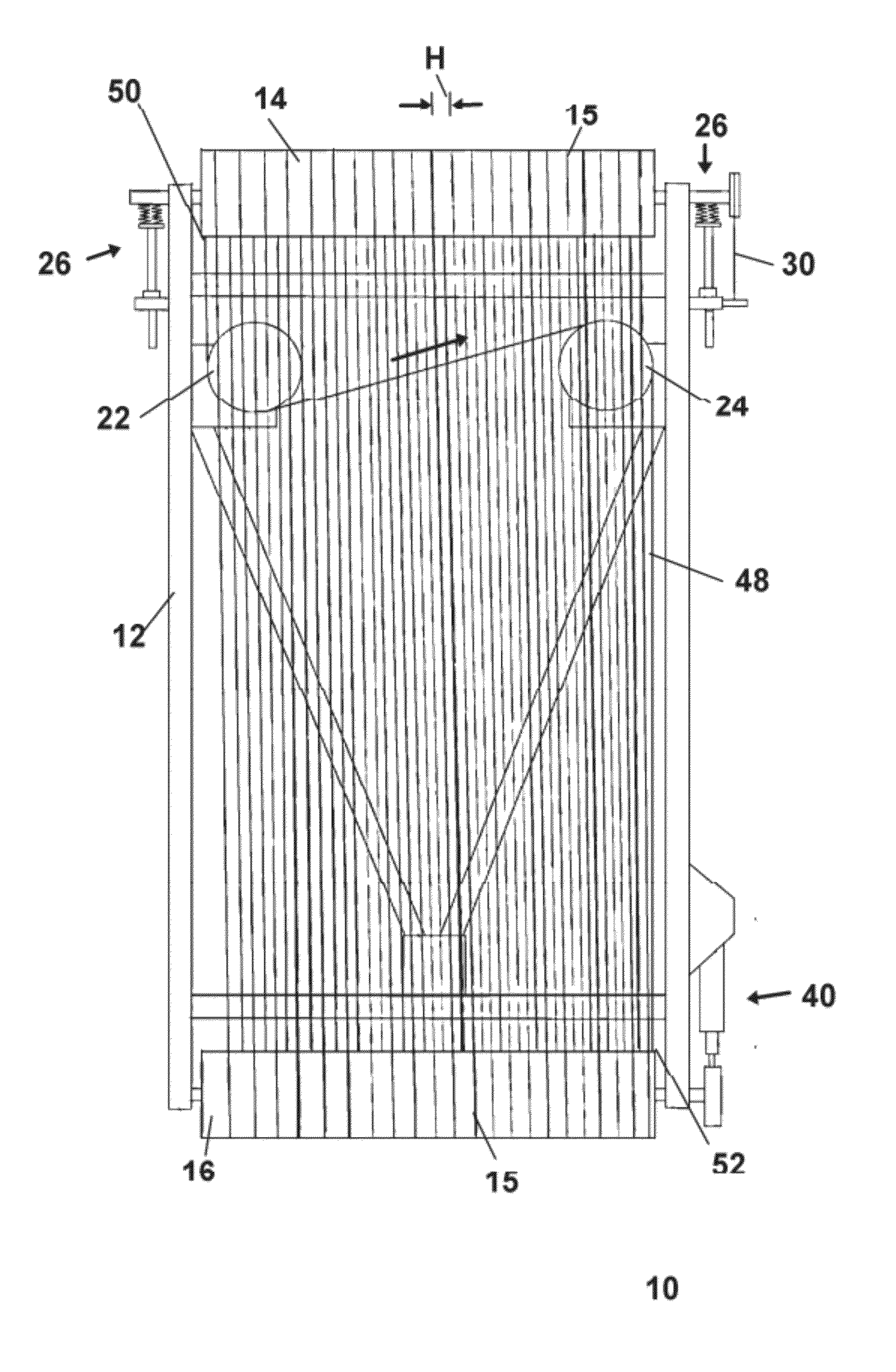
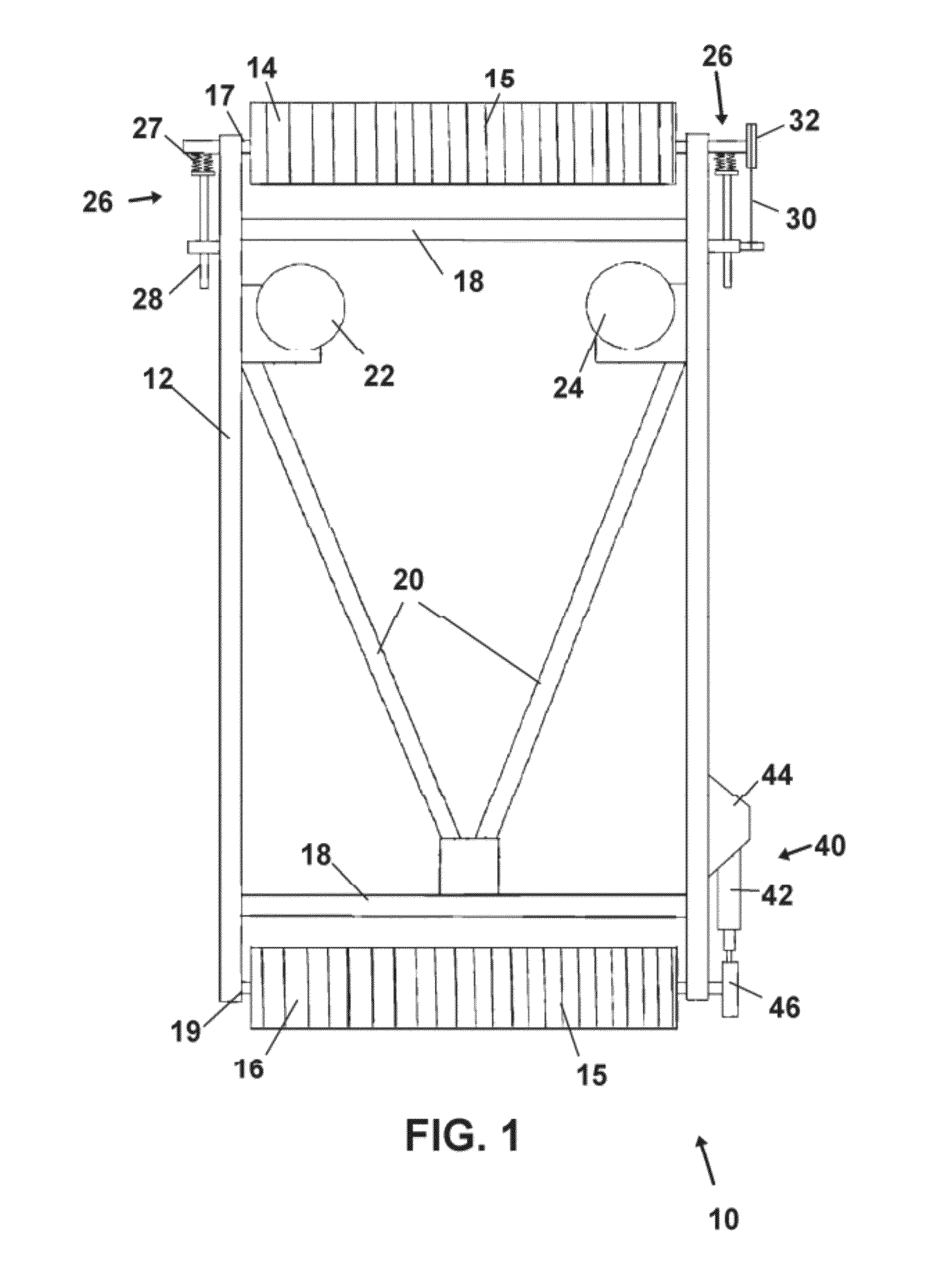
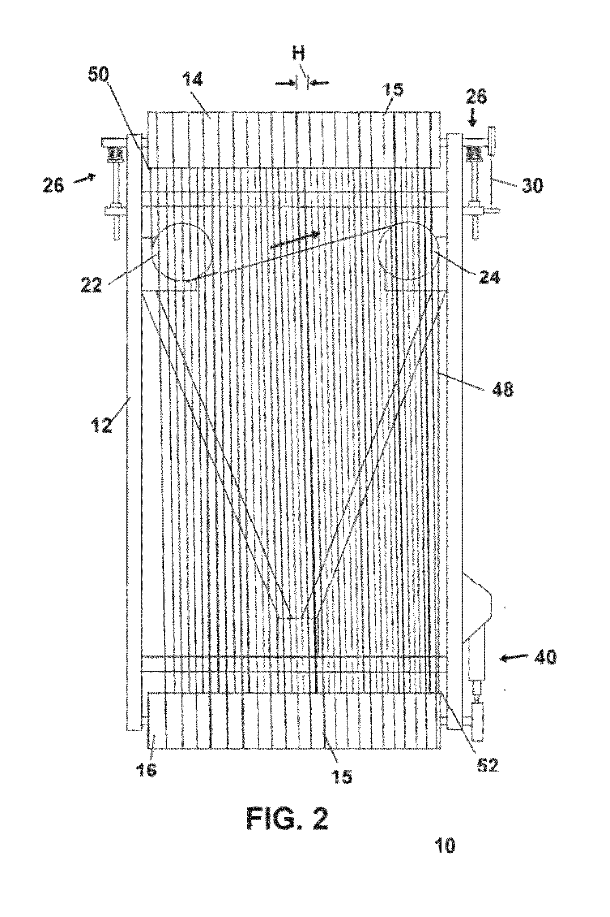
[0038]Now referring to drawings in FIGS. 1-6, wherein similar components are identified by like reference numerals, there is seen in FIG. 1 a top view of the frame 12 of the device 10 where the single strand of wire 48 forming the conveyor surface is removed for clarity. It should be noted that the use of the word “wire” is to mean any single strand or multi-strand metal or textile thread, cable, or wire, capable of tensioned engagement in the device 10 herein and in no manner should it be limiting.

[0039]First rotating drum 14 and second rotating drum 16 rotating drums are rotatably engaged to the frame 12 at axles 17 and 19 respectively. Means to register and maintain the positions and spacing of the wire around the drums are shown as guide grooves 15 formed into the surface of the drums 14,16. However, it is envisioned that other means to maintain the spacing of the wires during ingress and egress from the drums 14 and 16, can be employed, such as a grooved bar inline with the inc...


PUM


Abstract

A conveying surface operating in a fashion of a conveying belt. The surface is formed to provide movement of material on the surface between two rollers. The conveying surface is formed by a continuous wire stretching in individual substantially parallel strands, between spiraled communications around the first roller and second roller. Spacing of the individual parallel strands of wire yields uninterrupted gaps for airflow therethrough and tensioning of the wire between the rollers eliminates sagging. The surface may be cleaned while moving by cleaning a return section of the wire strand between the rollers.

Description

[0001]This application claims priority to U.S. Provisional Patent Application Ser. No. 61 / 450,978 filed on Mar. 9, 2011, and incorporated herein in its entirety by this reference.BACKGROUND OF THE INVENTION[0002]1. Field of the Invention[0003]The present invention relates to transport conveyors and more particularly to a transport conveyor for drying and / or dehydrating food such as fruits and vegetables. The device operates to convey food through the process using a conveying surface composed of a single endless wire running in a continuous looping fashion and improves significantly on the air passage to the food during the process.[0004]2. Prior Art[0005]A food dehydrator is an apparatus which removes moisture from food to aid in its preservation. Generally, a food dehydrator uses heat and air flow past the food being dehydrated to remove and thereby reduce the water content of foods. The water content of most food is usually very high, typically 80% to 95% for various fruits and v...

Claims


Application Information

Patent Timeline
IPC IPC(8): B65G15/10B65G23/44B65G45/10
CPCB65G23/44B65G15/105B65G45/10
Inventor JOHNSON, JR., NOLTON C.
Owner JOHNSON JR NOLTON C
Learn More