Apparatus for reducing drag on a vehicle

a technology for reducing drag and vehicles, applied in the direction of roofs, transportation and packaging, vehicle arrangements, etc., can solve the problems of increasing drag and far more drag, and achieve the effect of reducing drag and reducing drag on vehicles

Inactive Publication Date: 2012-09-06
BENTON CRAIG R
View PDF9 Cites 30 Cited by
  • Summary
  • Abstract
  • Description
  • Claims
  • Application Information

AI Technical Summary

Benefits of technology

[0010]There remains an unmet need to more effectively reduce the drag caused by the low pressure area that is created behind a moving vehicle. Aspects of the present invention provide an apparatus for reducing drag on vehicles via features that may be mechanically actuated. Another variation in accordance with aspects of the current invention includes a foil disposed in a retracted position that may be deployed into an expanded position. According to various example aspects, the foil may be activated via a series of arms and pivots, and the foil may deploy in several segments from a retracted position to a fully expanded position.

Problems solved by technology

When a vehicle is in motion, a low pressure area generally forms at the rear of the vehicle, and the low pressure area may result in increased drag.
For example, the square-shaped rear end of a semi-tractor trailer may cause far more drag than the round-shaped end of a sports car.

Method used


Image

  • Apparatus for reducing drag on a vehicle
  • Apparatus for reducing drag on a vehicle
  • Apparatus for reducing drag on a vehicle

Examples


Embodiment Construction

[0025]Various features and advantages in accordance with aspects of this invention are described in, or will be apparent from, the following detailed description of various example implementations.

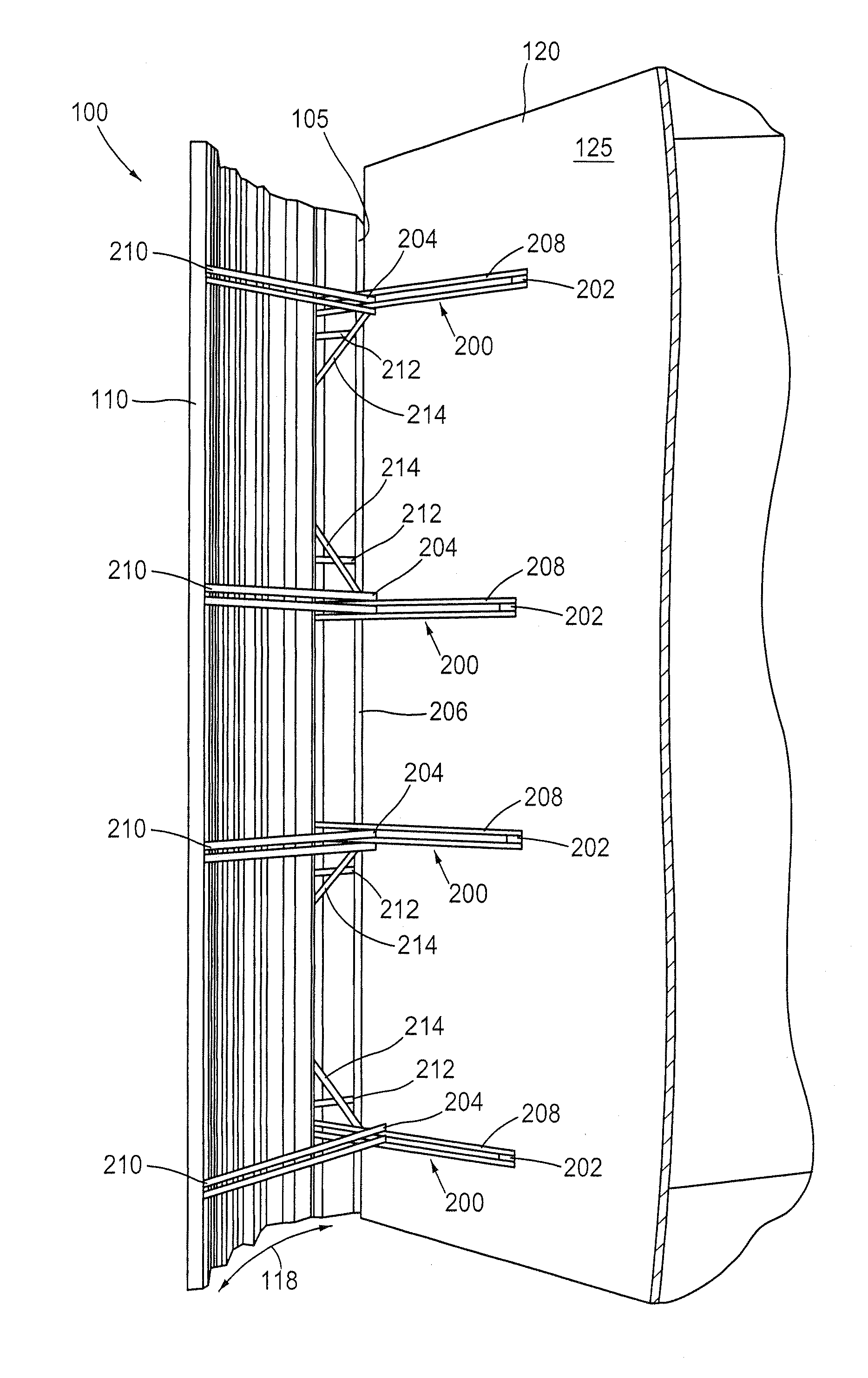
[0026]FIGS. 1A-2B are perspective and top views, respectively, of an apparatus for drag reduction 100, according to various aspects of the present invention, shown in an expanded position and a retracted positions. In FIGS. 1A and 1B, a sectioned thin profile wind diverting material 110 (each wind diverting material also interchangeably referred to herein as a “airfoil”) is shown as fully expanded. The foil may comprise a single sheet of material or may be formed by a series of segments that are deployed as a result of the expansion of the foil 110. A more detailed description of an example structure of the segmented foil 110 is given in applicant's co-pending U.S. patent application Ser. No. 12 / 969,456, which is incorporated by reference herein. In the expanded position, the advantageous ...


PUM


Abstract

An apparatus for reducing atmospheric drag on a vehicle. The apparatus includes an airfoil having a receiving feature, wherein the airfoil is attachable with a back portion of the vehicle. The apparatus includes at least one extender attachable with the back portion of the vehicle, and a slide arm attached to the at least one extender and mateable with the recess portion of the airfoil. The apparatus is configured such that when the slide arm is disposed in the receiving portion of the airfoil, the airfoil is in an extended position relative to the back of the vehicle. The apparatus is further configured such that applying a force on the airfoil in a direction substantially perpendicular to the back portion of the vehicle buckles the airfoil, thereby lifting the slide arm from the recess and moving the airfoil to a retracted position.

Description

[0001]This application is a continuation-in-part of U.S. patent application Ser. No. 12 / 969,456, filed on Dec. 15, 2010, and titled “Apparatus for Reducing Drag on a Vehicle” (the '456 application), which claims priority to U.S. Provisional Patent Application No. 61 / 374,418, filed Aug. 17, 2010, titled “Apparatus for Reducing Drag on a Vehicle,” and the '456 application is a continuation-in-part of U.S. patent application Ser. No. 11 / 653,536, filed Jan. 16, 2007, titled “Apparatus for Reducing Drag on Vehicles,” now U.S. Pat. No. 7,862,102. The disclosures of the above-recited prior applications are each hereby incorporated herein by reference in their entirety.BACKGROUND OF THE INVENTION[0002]1. Field of Invention[0003]Aspects of this invention relate generally to the field of atmospheric drag reduction, and more particularly to an apparatus for reducing drag on vehicles.[0004]2. Background of the Invention[0005]When a vehicle is in motion, a low pressure area generally forms at th...

Claims


Application Information

Patent Timeline
Patent Type & Authority Applications(United States)
IPC IPC(8): B62D35/00
CPCB62D35/001
Inventor BENTON, CRAIG R.
Owner BENTON CRAIG R
Why Eureka
Try Eureka