
Method and device for automatically adapting a write cycle in a digital printing machine

Inactive Publication Date: 2012-08-30
EASTMAN KODAK CO
View PDF2 Cites 4 Cited by
  • Summary
  • Abstract
  • Description
  • Claims
  • Application Information

AI Technical Summary

Benefits of technology

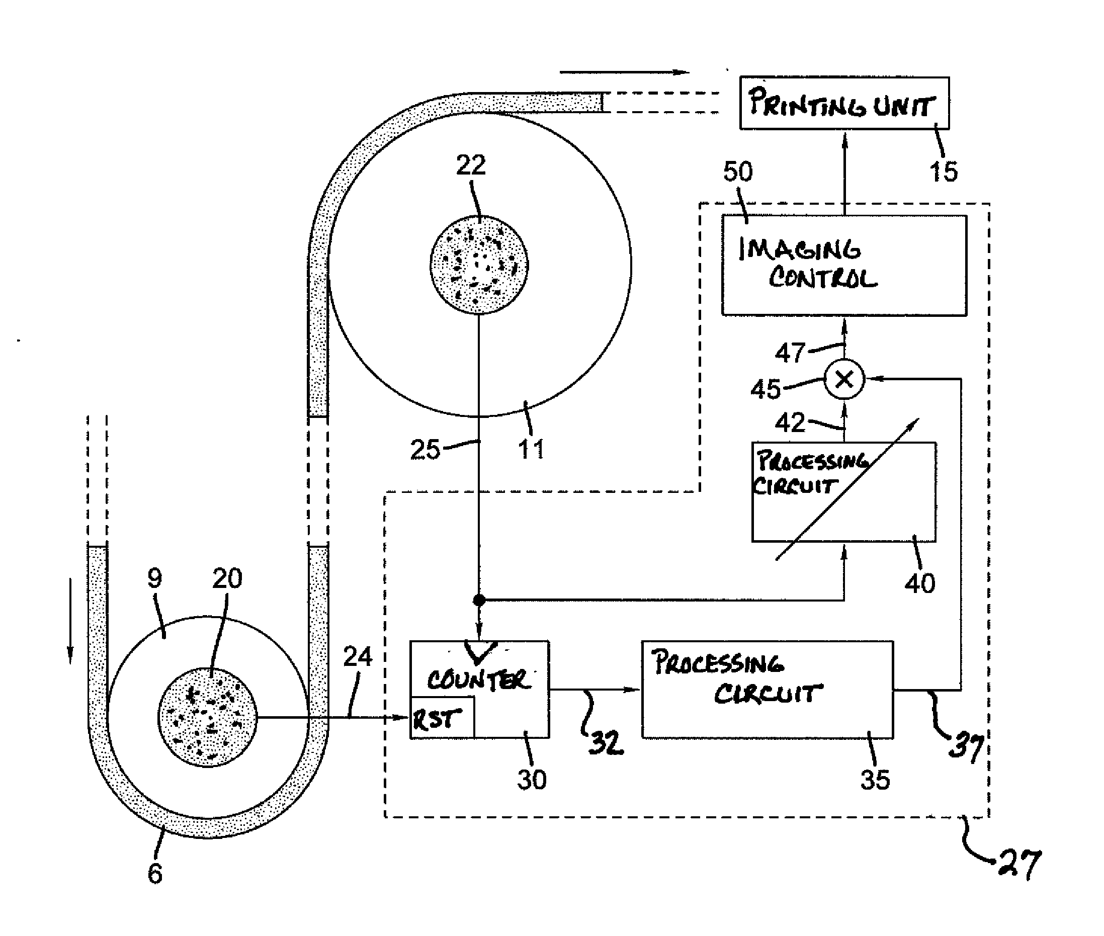
[0021]Such a method enables the highly accurate adaptation of the write cycle of a print head in a printing machine to the actual speed of the web-shaped medium, which is the printing material in a roll printing machine, because it automatically includes the thickness of the medium in the determination of the write cycle based on the rotational speed ratio. Furthermore it is taken into consideration that, depending on the roller diameter, the printing material thickness has a varying effect on the ratio between the printing material speed and the rotational speed of the roller, so that printing material webs having varying thicknesses generate varying rotational speed ratios.
[0026]Preferably, for automatically adapting the write cycle during operation, an adaptation value is determined using the nominal rotational speed ratio and the rotational speed ratio determined during operation, the value is disposed to adapt the nominal write cycle. This enables a simple and rapid adaptation to the rotational speed ratios determined during operation in order to be able to automatically respond to changing thicknesses of the printing material in a simple manner.
[0029]As opposed to this, the first encoder can, for example, output zero pulses only, where a zero pulse is a pulse that is output after one full rotation, i.e., 360°. Such an encoder can have a simple design and achieve high accuracy. However, the first encoder can also output several signals with one complete rotation of the transport or guide roller, e.g., after each 90°. Advantageously, the pulses should be output equidistantly, and the distance between successive pulses should be known so exactly as to have a determined ratio to the resolution of the second encoder. The use of several pulses during one rotation of the first transport or guide roller can be used for a more rapid adaptation of the write cycle to the actual web speed of the printing web; however, this increases the demands on the first encoder.
[0031]The present invention includes a device for automatically adapting a write cycle to a movement of a web-shaped medium in a digital printing machine that is capable of automatically taking into consideration the thickness of the web-shaped medium for adaptation. The device can, like the method, be implemented in a roll printing machine or in a sheet printing machine. The device includes a first transport or guide roller having a known first diameter, the roller being connected to a first encoder, and includes a second transport or guide roller having a second known diameter, which is different from the first diameter, and is connected to a second encoder. Furthermore, the device includes a control unit that is capable of receiving pulses from the first and the second encoder and to determine therefrom a rotational speed ratio between the first and the second transport or guide rollers during operation, and to perform an adaptation of the write cycle by use of at least the determined rotational speed ratio. Such a device enables an automatic consideration of the thicknesses of a printing material in the determination of a write cycle for the application of images to the printing material.
[0034]In a simple design, the first encoder preferably includes a number of bars equal to 1.

Problems solved by technology

Printing materials having different thicknesses, however, result in different transport speeds because the thickness of the printing material contributes to the effective radius of the speedometer shaft.
If such differences are not taken into consideration in the aforementioned system, inaccuracies result regarding the adjustment between the line cycle and the speed of the printing material when the printing machine is operated with printing materials having different thicknesses.
Ultimately this leads to an elongation or compression of an image at the time of imaging because the write cycle is not exactly adjusted to the actual transport speed of the printing material.
An error of this order of magnitude is intolerable in high-quality printed products.
However, this procedure is time-consuming and labor-intensive, and the result is dependent on the care with which the machine operator is working.
Furthermore, this procedure has to be performed for each new roll of printing material and can thus not respond to changes within a roll of printing material.

Method used


Image

  • Method and device for automatically adapting a write cycle in a digital printing machine
  • Method and device for automatically adapting a write cycle in a digital printing machine
  • Method and device for automatically adapting a write cycle in a digital printing machine

Examples


Embodiment Construction

[0040]In the description hereinafter, information regarding location or direction primarily relates to the representations in the drawings and should thus not be viewed as restrictive; however, such information can also relate to preferred final arrangements.

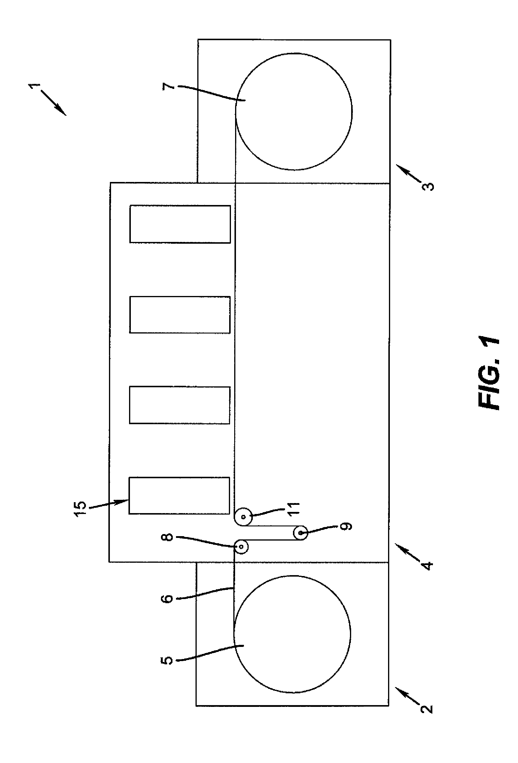
[0041]FIG. 1 is a schematic side view of a digital printing machine 1 for web-shaped printing materials 6. The printing machine 1 includes an unwinder 2, a winder 3, as well as an interposed printing region 4. A printing material roll 5 is rotatably supported in the unwinder 2, from where the printing material 6 is passed through the printing region 4 to a printing material take-up roll 7 in the winder 3.

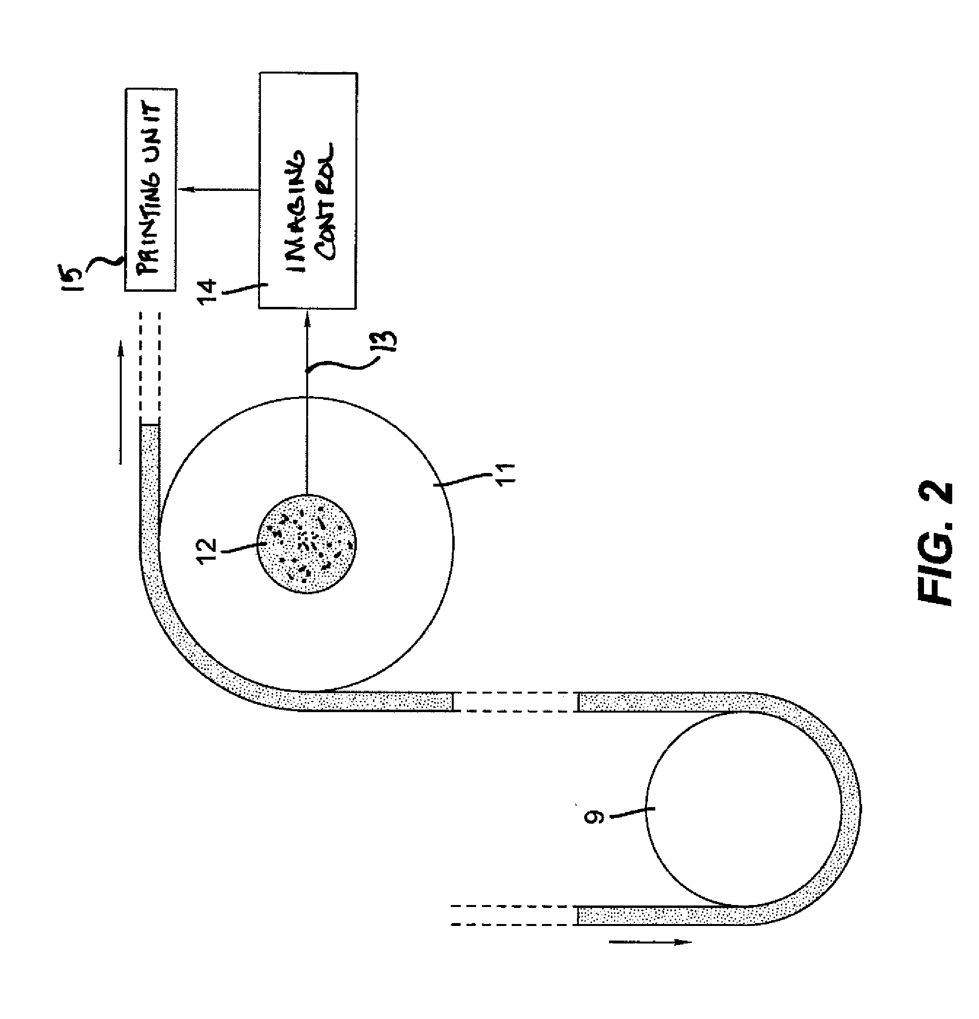
[0042]During the printing operation, the printing material 6 is conveyed from the printing material roll 5 to the printing material take-up roll 7, i.e., via a plurality of transport or guide rollers 8, 9, 11 in the printing region 4, only three of the rollers are shown to simplify the drawing. Hereinafter, for simplification, s...


PUM


Abstract

A method for automatically adapting a write cycle to a movement of a web-shaped medium in a digital printing machine, as a function of the thickness of the web-shaped medium guided around first and second transport or guide rollers, includes providing the first and second transport or guide rollers having a known diameters, the diameter of the second being different from the diameter of the first. A rotational speed ratio N(T) between the first and second transport or guide rollers (9, 11) is determined while the printing material (6) is guided around the transport or guide rollers (9, 11). The write cycle is determined at least with the use of the previously determined rotational speed ratio N(T).

Description

CROSS-REFERENCE TO RELATED APPLICATIONS[0001]This application is related to and claims priority of DE 102011012677.5 filed Feb. 28, 2011 and DE 102011017209.2 filed Apr. 15, 2011, which are hereby incorporated herein by reference in their entirety.FIELD OF THE INVENTION[0002]The present invention relates to a device and a method for automatically adapting a write cycle in a digital printing machine, where a write cycle is adapted to a movement of a web-shaped medium as a function of the thickness of the medium.BACKGROUND OF THE INVENTION[0003]In printing technology it is known, on the one hand, to print web-shaped printing materials and, on the other hand, to print separated sheet-shaped printing materials. When printing a web-shaped printing material, the printing material, as a rule, is taken off a roll and moved past one or more printing units of a printing machine, wherein a printing medium such as, for example, ink, is applied to the web-shaped printing material.[0004]In digita...

Claims


Application Information

Patent Timeline
IPC IPC(8): B41J15/00
CPCB41J11/0035B41J15/165B41J11/42
Inventor PETER, KARLHEINZ
Owner EASTMAN KODAK CO
Learn More