
Fixing device and image forming apparatus incorporating same

a technology of fixing device and image forming apparatus, which is applied in the direction of electrographic process apparatus, instruments, optics, etc., can solve the problems of faulty detection of the temperature of the fixing roller, -hole raising another problem, and detection error of the thermopil

Inactive Publication Date: 2012-08-30
RICOH KK
View PDF10 Cites 73 Cited by
  • Summary
  • Abstract
  • Description
  • Claims
  • Application Information

AI Technical Summary

Benefits of technology

[0008]This specification describes below an improved fixing device. In one exemplary embodiment of the present invention, the fixing device includes a fixing rotary body rotatable in a predetermined direction of rotation to radiate infrared rays; a pressing rotary body, rotatable in a direction counter to the direction of rotation of the fixing rotary body, pressed against the fixing rotary body to form a fixing nip therebetween through which a recording medium bearing a toner image is conveyed; a heater disposed opposite the fixing rotary body to heat the fixing rotary body; a t

Problems solved by technology

However, the thermopile raises a problem that it may detect not only infrared rays from the fixing roller but also infrared rays from the components other than the fixing roller, resulting in faulty detection of the temperature of the fixing roller.
Although effective for its intended purpose, the through-hole raises another problem.
When the steam and volatilized wax move from the fixing nip into the through-hole of the induction heater, they may adhere to the interior wall of the through-hole, causing detection error of the thermopile.

Method used


Image

  • Fixing device and image forming apparatus incorporating same
  • Fixing device and image forming apparatus incorporating same
  • Fixing device and image forming apparatus incorporating same

Examples


first embodiment

[0018]Referring now to the drawings, wherein like reference numerals designate identical or corresponding parts throughout the several views, in particular to FIG. 1, an image forming apparatus 1 according to the present invention is explained.

[0019]A description is now given of the structure of the image forming apparatus 1 with reference to FIG. 1.

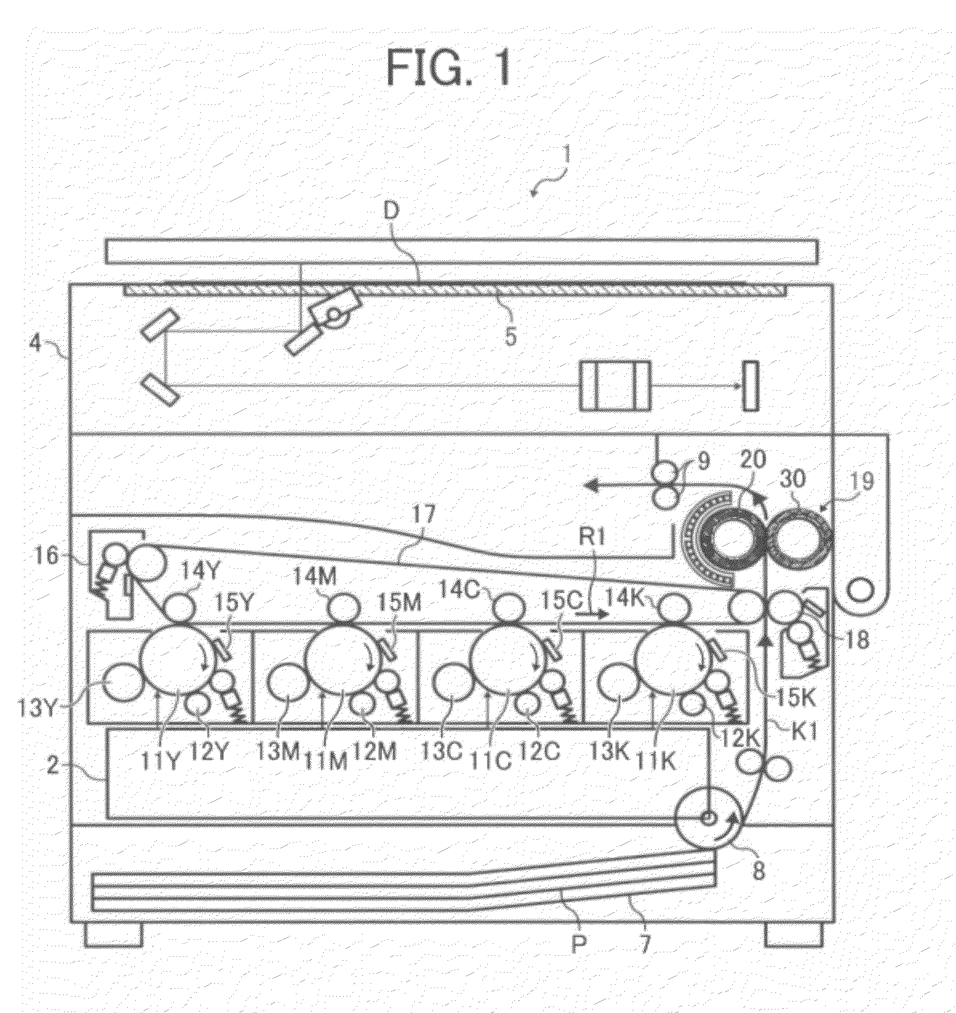
[0020]FIG. 1 is a schematic sectional view of the image forming apparatus 1. As illustrated in FIG. 1, the image forming apparatus 1 may be a copier, a facsimile machine, a printer, a multifunction printer having at least one of copying, printing, scanning, plotter, and facsimile functions, or the like. According to this exemplary embodiment, the image forming apparatus 1 is a tandem color copier for forming a color image on a recording medium by electrophotography. The image forming apparatus 1 includes an original document reader 4 disposed in an upper portion of the image forming apparatus 1 to read an image on an original document D ...

second embodiment

[0069]Referring to FIG. 4, the following describes a

[0070]FIG. 4 is a vertical sectional view of a thermopile 34S and a protector 74 according to the second embodiment. Unlike the thermopile 34 shown in FIG. 3 according to the first embodiment, the thermopile 34S according to the second embodiment has the protector 74 attached to the detecting face 34a of the thermopile 34S. The protector 74 prohibits adhesion of a foreign substance to the detecting face 34a of the thermopile 34S while allowing infrared rays to penetrate the protector 74. For example, the protector 74 is made of a material having fine pores such as Gore-Tex®. Accordingly, even when an atmosphere containing steam and volatilized wax reaches the thermopile 34S through the tube 35 depicted in FIG. 3, the protector 74 prevents the steam and volatilized wax from adhering to the detecting face 34a of the thermopile 34S while allowing air containing heat and infrared rays to penetrate the protector 74. Consequently, the th...

third embodiment

[0071]Referring to FIG. 5, the following describes a

[0072]FIG. 5 is a vertical sectional view of the thermopile 34 and a tube 35T according to the third embodiment. Unlike the tube 35 shown in FIG. 3 according to the first embodiment, the tube 35T according to the third embodiment is attached with a filter 76 that allows penetration of infrared rays only. As shown in FIG. 5, the filter 76 is attached to a circumferential edge creating the inlet 35A of the tube 35T which faces the fixing roller 20. Alternatively, the filter 76 may be attached to other position. The filter 76 prevents adhesion of a foreign substance to the detecting face 34a of the thermopile 34 and protects the thermopile 34 at decreased costs without modification of the configuration of the thermopile 34. The filter 76 is made of a heat resistant material such as polycarbonate, glass, and resin. The filter 76 has a thickness not greater than about 200 micrometers that maintains a predetermined permeability of infrar...


PUM


Abstract

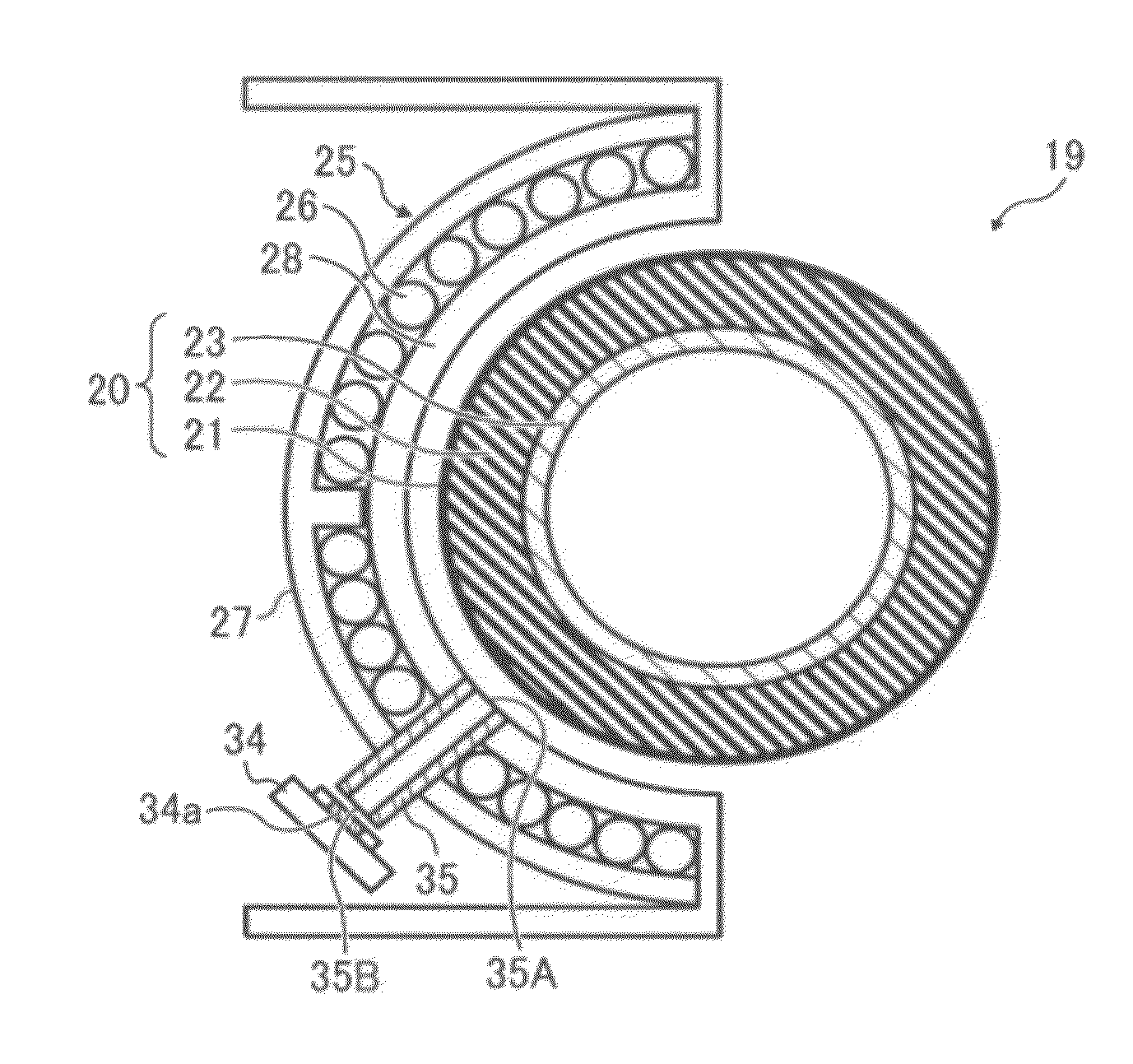
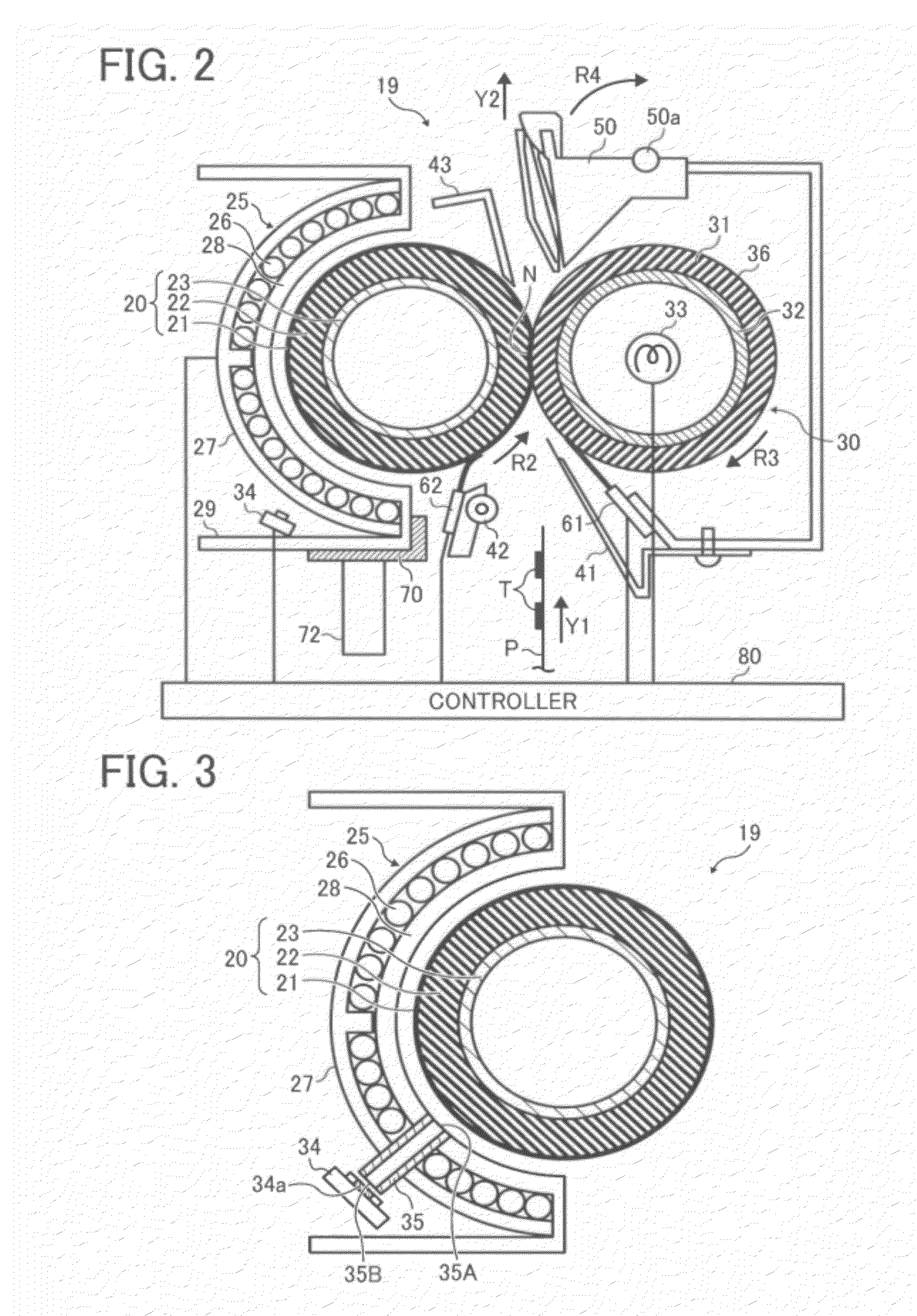
A fixing device includes a fixing rotary body rotatable in a predetermined direction of rotation to radiate infrared rays; a pressing rotary body, rotatable in a direction counter to the direction of rotation of the fixing rotary body, pressed against the fixing rotary body to form a fixing nip therebetween through which a recording medium bearing a toner image is conveyed; a heater disposed opposite the fixing rotary body to heat the fixing rotary body; a temperature detector spaced apart from the fixing rotary body to detect a temperature of the fixing rotary body based on the infrared rays from the fixing rotary body and disposed below the fixing nip in a vertical direction; and a tube disposed between the fixing rotary body and the temperature detector, the tube through which the infrared rays from the fixing rotary body enter the temperature detector.

Description

CROSS-REFERENCE TO RELATED APPLICATIONS[0001]This patent application is based on and claims priority pursuant to 35 U.S.C. §119 to Japanese Patent Application No. 2011-040631, filed on Feb. 25, 2011, in the Japanese Patent Office, the entire disclosure of which is hereby incorporated herein by reference.FIELD OF THE INVENTION[0002]Exemplary aspects of the present invention relate to a fixing device and an image forming apparatus, and more particularly, to a fixing device for fixing a toner image on a recording medium and an image forming apparatus including the fixing device.BACKGROUND OF THE INVENTION[0003]Related-art image forming apparatuses, such as copiers, facsimile machines, printers, or multifunction printers having at least one of copying, printing, scanning, and facsimile functions, typically form an image on a recording medium according to image data. Thus, for example, a charger uniformly charges a surface of an image carrier; an optical writer emits a light beam onto th...

Claims


Application Information

Patent Timeline
IPC IPC(8): G03G21/20G03G15/20
CPCG03G15/2039
Inventor YUASA, SHUUTAROHEHARA, MASANAOOGAWA, TADASHIUENO, SATOSHISEO, HIROSHIKAWATA, TEPPEITAMAKI, SHUNTAROHHASE, TAKAMASASAITO, KAZUYAYAMAJI, KENSUKE
Owner RICOH KK
Learn More