
System Apparatus and Method for Interconnecting TDM and Frame/Packet Communication Networks

a technology of system apparatus and communication network, which is applied in the field of system apparatus and method for interconnecting tdm and frame/packet communication network, can solve the problems of difficult to imagine that the shift to next-generation network will happen immediately, and achieve the effects of improving communication quality, improving network management convenience, and expanding the service region supported

Inactive Publication Date: 2012-08-30
HITACHI LTD
View PDF10 Cites 4 Cited by
  • Summary
  • Abstract
  • Description
  • Claims
  • Application Information

AI Technical Summary

Benefits of technology

This solution enhances communication quality, improves network management convenience, and expands service capabilities in packet networks, ensuring reliability and flexibility, allowing seamless transition to next-generation networks without altering the operating system.

Problems solved by technology

However, considering that synchronous networks using PDH and SDH have been widely used as standard technology both in Japan and other countries, it is difficult to imagine that the shift to next generation networks will happen immediately.

Method used


Image

  • System Apparatus and Method for Interconnecting TDM and Frame/Packet Communication Networks
  • System Apparatus and Method for Interconnecting TDM and Frame/Packet Communication Networks
  • System Apparatus and Method for Interconnecting TDM and Frame/Packet Communication Networks

Examples


first embodiment

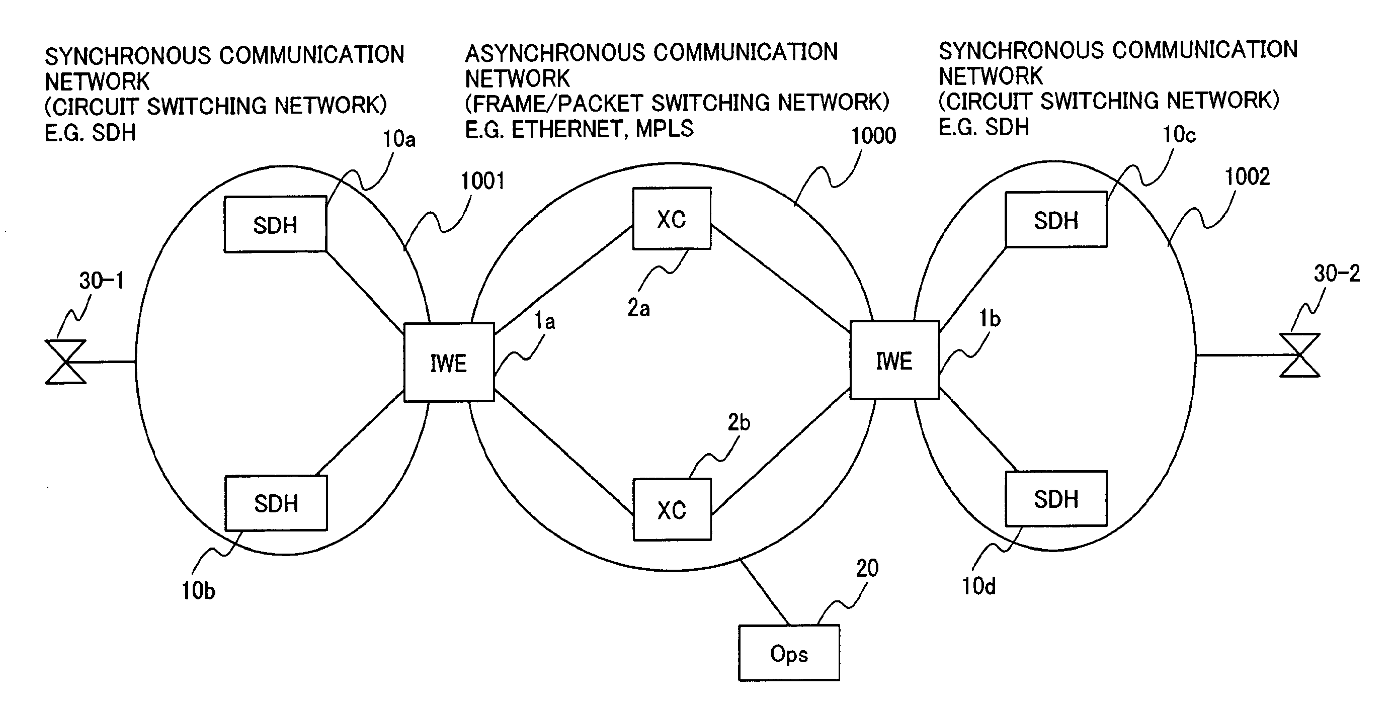
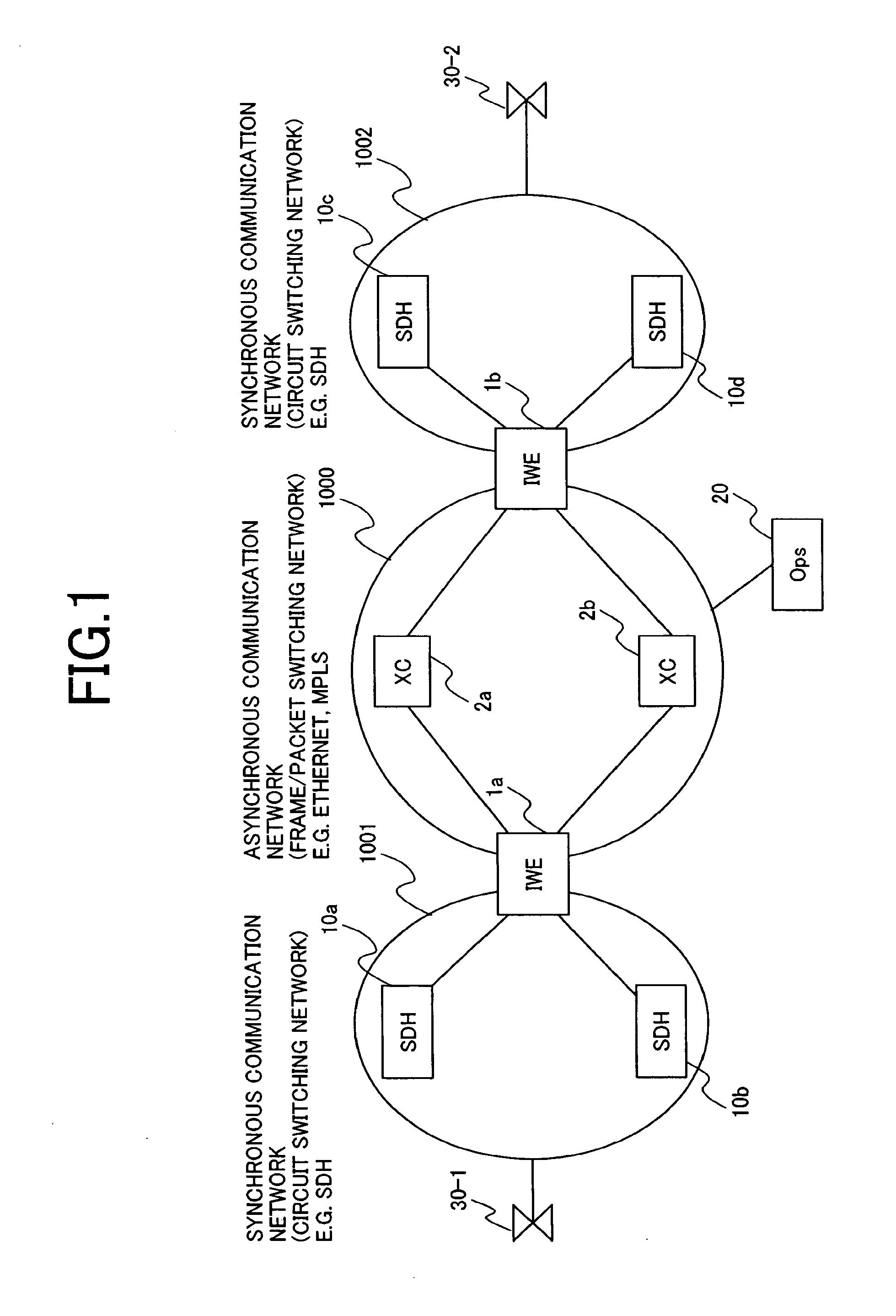
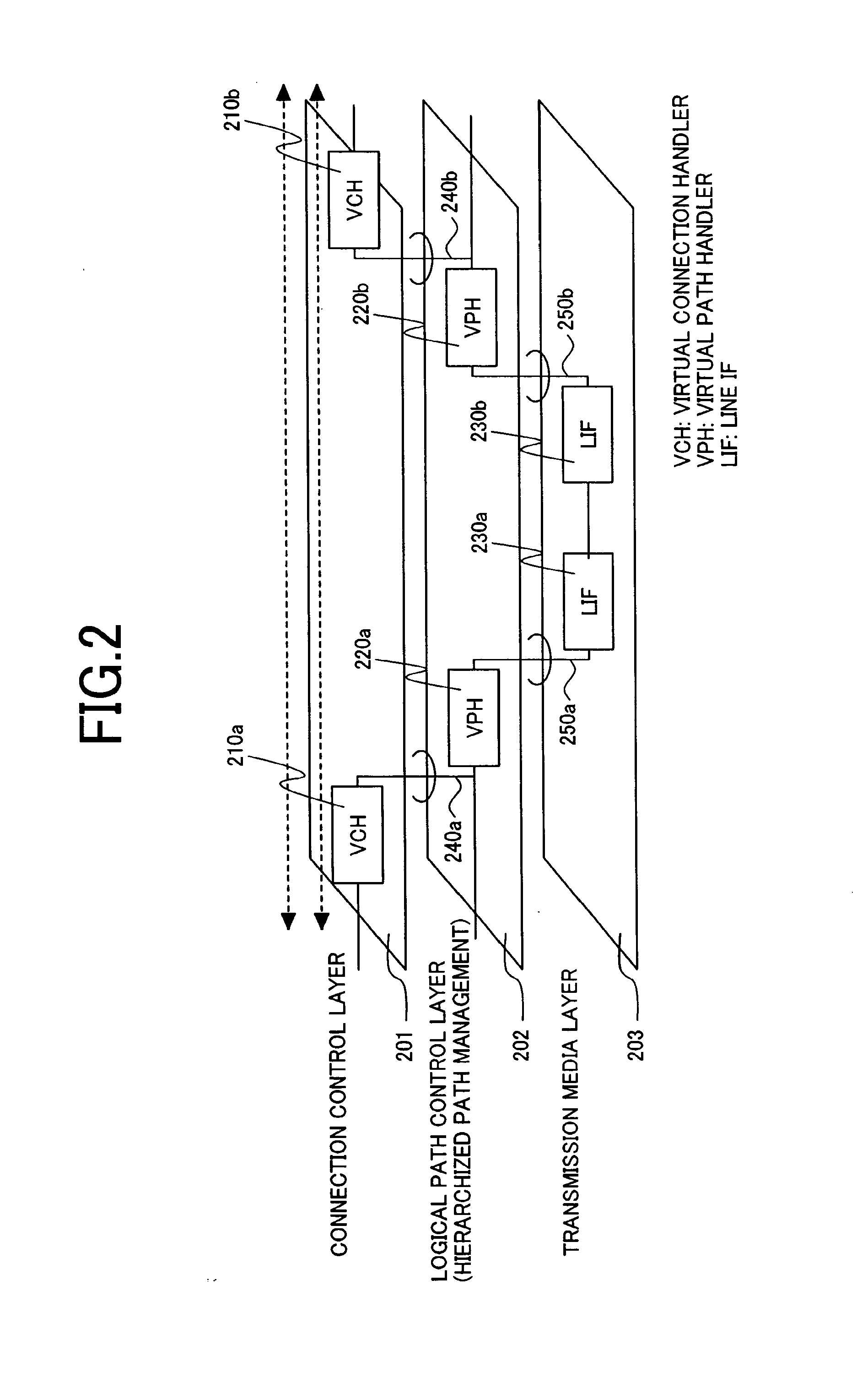
[0059]FIG. 5 shows the protocol stack in this invention. On the synchronous network side of IWE1a and IWE1b, hierarchized path control is performed by sections 503-1, 503-2 and paths 502-1, 502-2 managed by SOH (Section Overhead) and POH (Path Overhead) of an STM synchronous multiplexing frame. IWE has a physical circuit 501-1 on the synchronous network side, and a physical circuit 510a on the frame communications network side. For example, the former accommodates synchronous circuits, such as E1 and T1, and the latter accommodates packet communication lines, such as Ethernet. Within the packet communication network, a tag (label) for logically building a circuit is inserted in layers higher than the data link layer of an OSI reference model. For example, in a L2 network, these logical paths can be built using a VLAN (Virtual Local Area Network) tag, and in a MPLS (Multiprotocol Label Switching) network, they can be built using a label. Hence, in the packet communication network, th...

second embodiment

[0063]FIG. 6 is a diagram describing the hierarchized logical path control in the asynchronous network. The network configuration of the example is identical to that of the description of FIG. 3.

[0064]Here, a flow (session) ID which is consistent within the asynchronous network in the setup of the high level path ID is used. The low level path IDs AU-FR1 (311), AU-FR2 (312) are identical to those of the first embodiment (FIG. 3).

[0065]The multiplexing method from the synchronous frames in the IWE1a to the asynchronous frames is identical to that of the first embodiment (FIG. 3). A flow is first identified for destination identification. For this purpose, the channel defined by the synchronous network is extracted from the phase information obtained by the AU pointer and TU pointer. After selecting a suitable path from the delivery paths which can reach the destination (opposite IWE) and generating frames, the frames are sent to the asynchronous network.

[0066]TU-FR (611) which is a h...


PUM


Abstract

An interconnection between fully synchronous networks and next-generation frame communications networks is disclosed. A means of bidirectional frame format conversion between a synchronous multiplexing system and a logical multiplexing system is provided, along with a method of transmitting data between different networks on a path as if it were being transmitted in the same network. Further, when converting network control information in an STM network into data suitable for a packet network, even across the boundary of a synchronous multiplexing system and a logical multiplexing system, a unified communication management means is provided over the whole path.

Description

CLAIM OF PRIORITY[0001]This application is a continuation of U.S. patent application Ser. No. 11 / 339,449, filed Jan. 26, 2006, which in turn claims the priority of Japanese application JP 2005-257244 filed on Sep. 6, 2005. The entire disclosure of each of the above-identified applications is incorporated herein by reference.FIELD OF THE INVENTION[0002]This invention relates to an interworking method and device which relay communication between networks with different communication methods. In particular, it relates to a method and device which interconnect a synchronous network which performs synchronous multiplexing frame communication, with an asynchronous network which performs variable-length frame or packet communication. This invention further relates to a logical path management method which hierarchically uses an identifier in order to enhance compatibility with a synchronous multiplexing frame in the asynchronous network which performs connection-less communication. This in...

Claims


Application Information

Patent Timeline
Patent Type & Authority Applications(United States)
IPC IPC(8): H04L12/56H04L12/66
CPCH04J3/1617H04L45/04H04J2203/0083
Inventor MIZUTANI, MASAHIKOASHI, YOSHIHIROTAKASE, MASAYUKIIWAMURA, ATSUSHITANAKA, AKIHIKOENDO, HIDEKIKAZAWA, TOHRU
Owner HITACHI LTD
Learn More