
Method and apparatus for compensating for timing synchronization error in a communication system

a communication system and timing synchronization technology, applied in the field of communication system methods and apparatus, can solve the problems of indoor picocells having difficulty in accurately setting timing synchronization, unable to use gps, and difficulty in setting timing synchronization using gps

Inactive Publication Date: 2012-08-30
SAMSUNG ELECTRONICS CO LTD
View PDF8 Cites 3 Cited by
  • Summary
  • Abstract
  • Description
  • Claims
  • Application Information

AI Technical Summary

Benefits of technology

[0014]Aspects of the present invention are to address at least the above-mentioned problems and / or disadvantages and to provide at least the advantages described below. Accordingly, an aspect of the present invention is to provide a method and apparatus for compensating for a timing synchronization error in a communication system.
[0015]Another aspect of the present invention is to provide a timing synchronization error compensation method and apparatus for improving cell scanning performance of a User Equipment (UE) in a communication system.
[0016]Still another aspect of the present invention is to provide a timing synchronization error compensation method and apparatus for improving timing synchronization setting and channel estimation performances of a UE during Multicast and Broadcast Service (MBS) provision in a communication system.

Problems solved by technology

Generally, in a communication system, a Base Station (BS) of an indoor picocell has difficulty in accurately setting timing synchronization, compared with a BS of a macrocell.
The reason is that while the macro BS sets timing synchronization using a Global Positioning System (GPS), the indoor picocell BS is unlikely to be able to use the GPS and thus has difficulty in setting timing synchronization using the GPS.
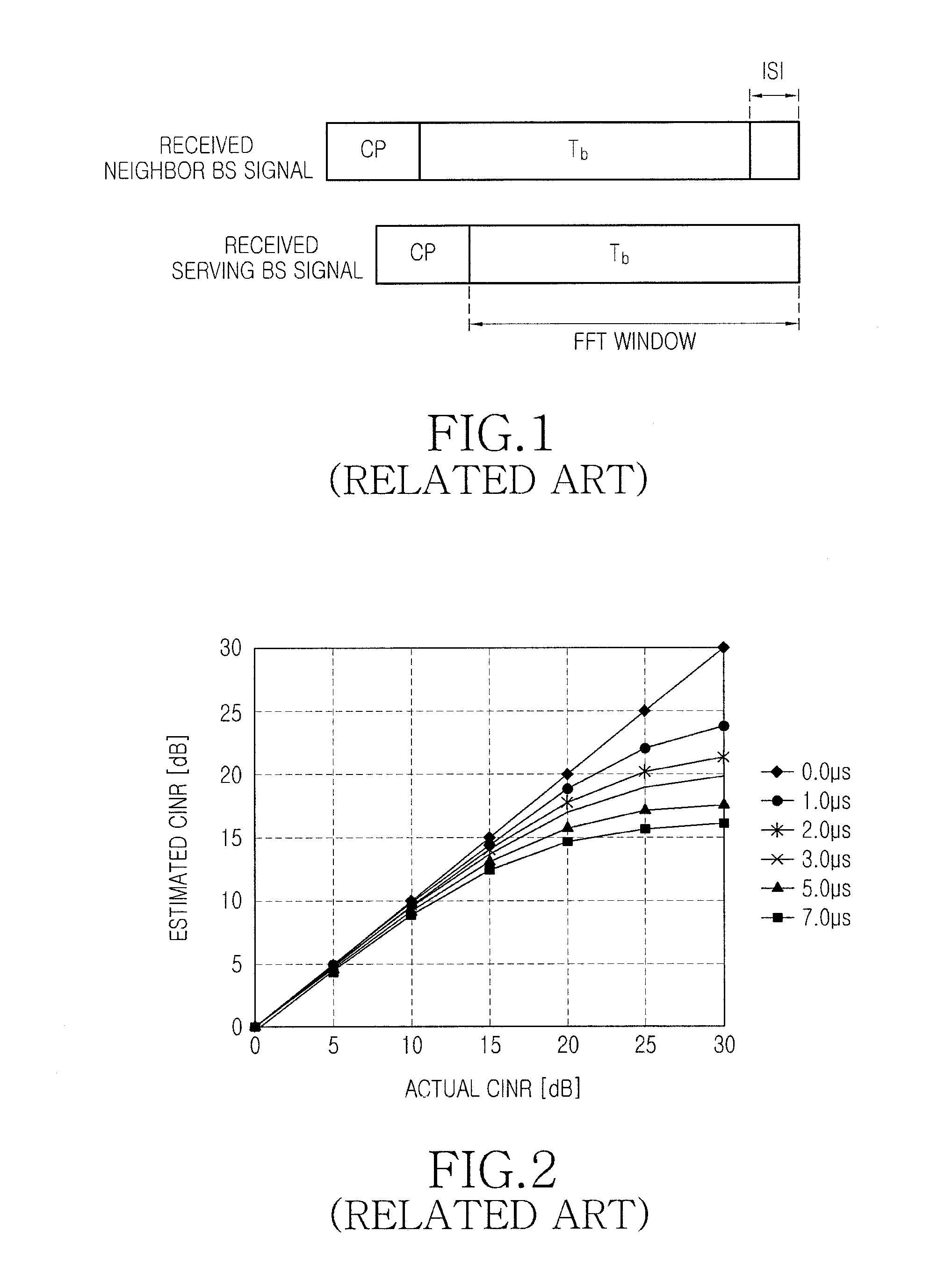
An increase in the timing difference between received BS signals may give rise to various problems.
One of the typical problems is that cell scanning performance of a User Equipment (UE) degrades, and another problem is that during Multicast and Broadcast Service (MBS) provision, an error may occur in timing synchronization setting and channel estimation by a UE.
In this case, the degradation of cell scanning performance may act as a fatal cause of reducing performance of the Mobile WiMAX communication system.

Method used


Image

  • Method and apparatus for compensating for timing synchronization error in a communication system
  • Method and apparatus for compensating for timing synchronization error in a communication system
  • Method and apparatus for compensating for timing synchronization error in a communication system

Examples


Embodiment Construction

[0035]The following description with reference to the accompanying drawings is provided to assist in a comprehensive understanding of exemplary embodiments of the invention as defined by the claims and their equivalents. It includes various specific details to assist in that understanding but these are to be regarded as merely exemplary. Accordingly, those of ordinary skilled in the art will recognize that various changes and modifications of the embodiments described herein can be made without departing from the scope and spirit of the invention. In addition, descriptions of well-known functions and constructions are omitted for clarity and conciseness.

[0036]The terms and words used in the following description and claims are not limited to the bibliographical meanings, but, are merely used by the inventor to enable a clear and consistent understanding of the invention. Accordingly, it should be apparent to those skilled in the art that the following description of exemplary embodi...


PUM


Abstract

A method for performing timing synchronization error compensation by a base station in a communication system, in which if there is a need for timing synchronization error compensation of a user equipment, the base station generates a message related to the timing synchronization error compensation, and broadcasts the generated message to the user equipment. In this manner, the base station can notify the user equipment of the need for timing synchronization error compensation in the communication system.

Description

PRIORITY[0001]This application is a National Stage application under 35 U.S.C. §371 of an International application filed on Oct. 29, 2010 and assigned application No. PCT / KR2010 / 007563, and claims the benefit under 35 U.S.C. §365(b) of a Korean patent application filed in the Korean Industrial Property Office on Oct. 29, 2009 and assigned Serial No. 10-2009-0103659, the entire disclosure of which is hereby incorporated by reference.BACKGROUND OF THE INVENTION[0002]1. Field of the Invention[0003]The present invention relates generally to a method and apparatus for a communication system. More particularly, the present invention relates to a method and apparatus for compensating for a timing synchronization error in a communication system.[0004]2. Description of the Related Art[0005]Generally, in a communication system, a Base Station (BS) of an indoor picocell has difficulty in accurately setting timing synchronization, compared with a BS of a macrocell. The reason is that while the...

Claims


Application Information

Patent Timeline
Patent Type & Authority Applications(United States)
IPC IPC(8): H04W56/00H04W4/06
CPCH04W56/005
Inventor PARK, SI-HYUNYOU, HWA-SUN
Owner SAMSUNG ELECTRONICS CO LTD
Learn More