
Fire pulse circuit and method of use

a technology of fire pulses and circuits, which is applied in the field of printers, can solve the problems of physical damage of the heater receiving an excessive fire pulse and noticeable loss of print quality from the printer, and achieve the effect of preventing damage to the heater within the printer

Inactive Publication Date: 2012-08-30
FUNAI ELECTRIC CO LTD
View PDF3 Cites 13 Cited by
  • Summary
  • Abstract
  • Description
  • Claims
  • Application Information

AI Technical Summary

Benefits of technology

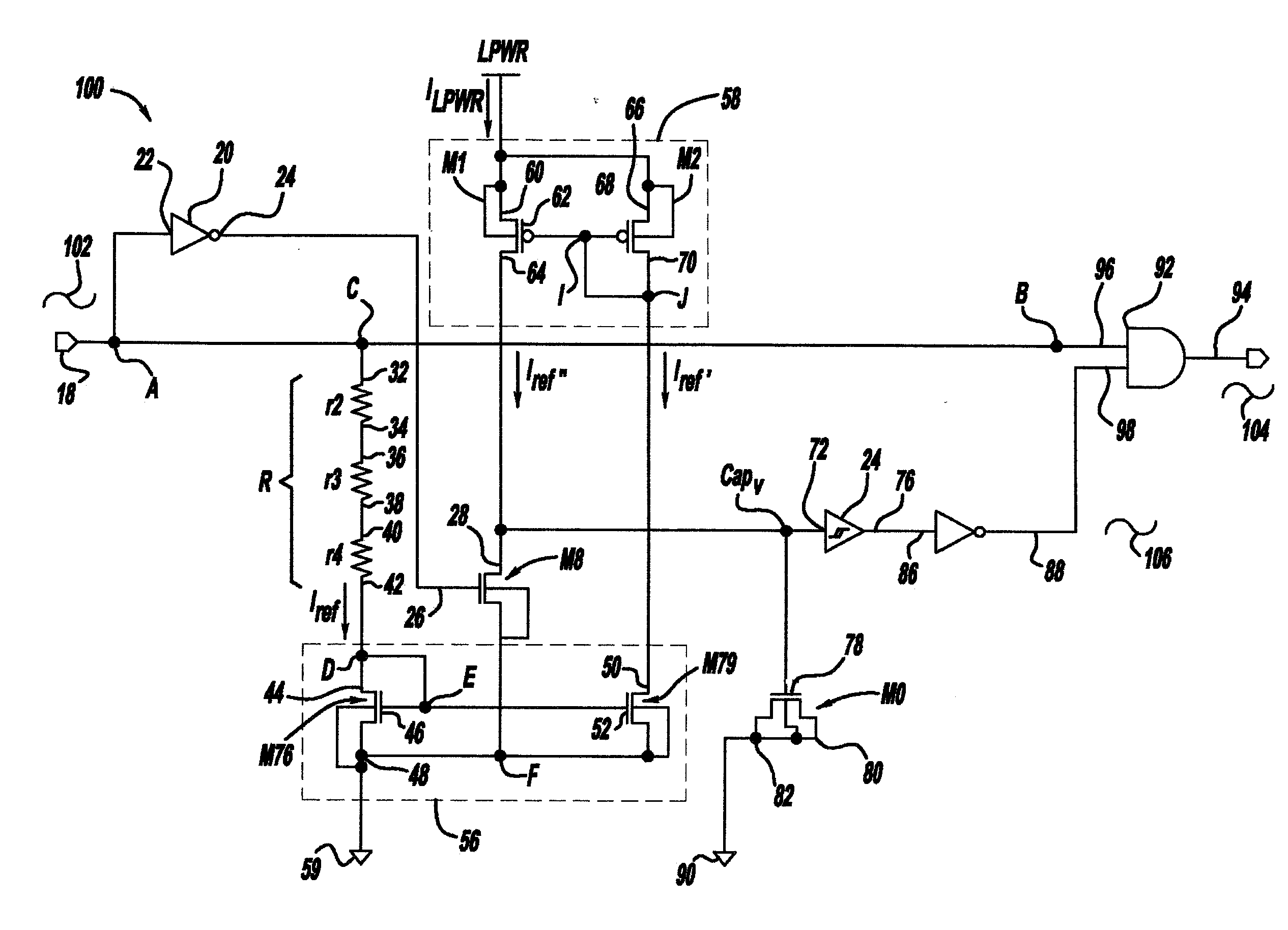
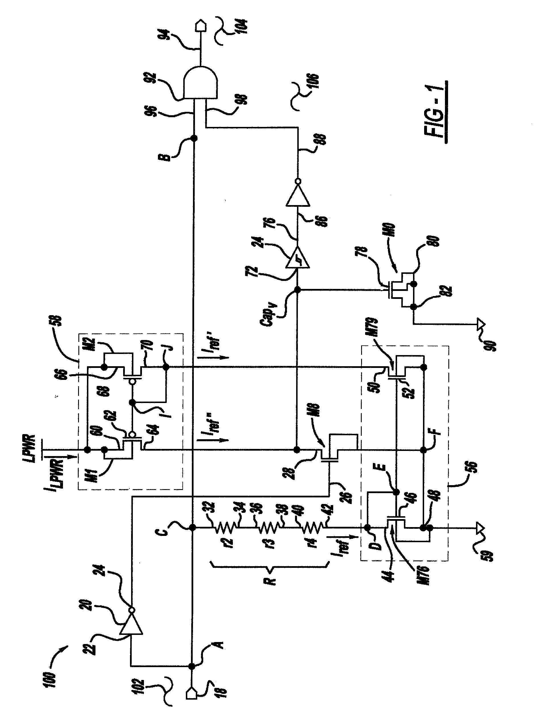
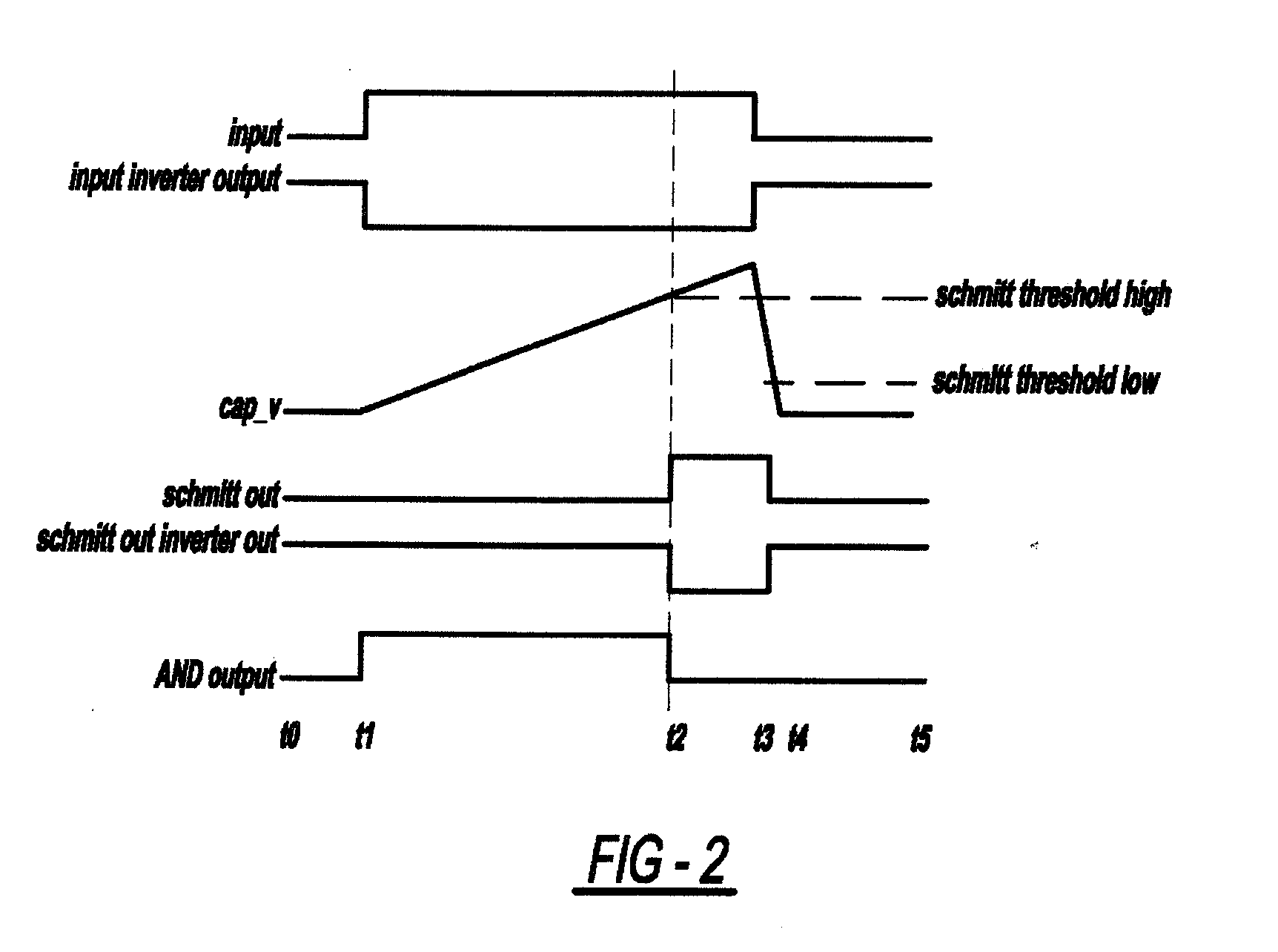
The patent describes a circuit and method for preventing damage to a heater in an inkjet printer. The circuit includes a logic AND gate that receives an input control signal and a fire truncation logic that removes a portion of the signal if the duration of the pulse exceeds a maximum allowable time. This prevents the heater from being damaged by a long duration of the pulse. The circuit can be made using both digital and analog components or all digital components. The technical effect of this invention is to protect the heater in the inkjet printer and improve the printing process.

Problems solved by technology

If the power FET receives an incorrect and excessive fire pulse duration then a heater receiving an excessive fire pulse may be physically damaged.
Once the heater is damaged, the heater will no longer print properly or the heater will lose the ability to print, resulting in a noticeable loss of print quality from the printer.

Method used


Image

  • Fire pulse circuit and method of use
  • Fire pulse circuit and method of use
  • Fire pulse circuit and method of use

Examples


Embodiment Construction

[0020]It is to be understood that the invention is not limited in its application to the details of construction and the arrangement of components set forth in the following description or illustrated in the drawings. The invention is capable of other embodiments and of being practiced or of being carried out in various ways. Also, it is to be understood that the phraseology and terminology used herein is for the purpose of description and should not be regarded as limiting. The use of “including,”“comprising,” or “having” and variations thereof herein is meant to encompass the items listed thereafter and equivalents thereof as well as additional items. Unless limited otherwise, the terms “connected,”“coupled,” and “mounted,” and variations thereof herein are used broadly and encompass direct and indirect connections, couplings, and mountings. In addition, the terms “connected” and “coupled” and variations thereof are not restricted to physical or mechanical connections or couplings...


PUM


Abstract

A fire pulse circuit for use in an inkjet printer includes an input control signal transmitted from a controller to a logic AND gate and to fire truncation logic; fire truncation logic adapted to truncate a pulse width of the input control signal to a maximum allowable pulse width if the duration of the pulse exceeds a maximum allowable time; a logic AND gate that receives inputs from both the input control signal and the fire truncation logic to produce an output fire pulse signal that operates to optimally fire an inkjet heater driver logic to heat the heater to nucleate ink from the print head. The circuit is formed from either a combination of digital and analog components or from exclusively digital components. A method of using the circuit to generate an output fire pulse to an inkjet heater driver logic is also disclosed.

Description

CROSS REFERENCES TO RELATED APPLICATIONS[0001]None.STATEMENT REGARDING FEDERALLY SPONSORED RESEARCH OR DEVELOPMENT[0002]None.REFERENCE TO SEQUENTIAL LISTING, ETC.[0003]None.BACKGROUND[0004]1. Field of the Invention[0005]The present invention relates generally to printers. More particularly, the present invention relates to ink jet printers having a fire pulse circuit that limits the width of any fire pulses that are deemed to be potentially damaging for a designed heater.[0006]2. Description of the Related Art[0007]Inkjet print heads require well-controlled timing of firing pulses entering a print head having an inkjet heater to maintain a consistent ink viscosity and jetting performance. CMOS thermal inkjet printers are actuated by data signals entering the print head. The current through an inkjet heater is controlled by a high power field effect transistor (power FET) that is actuated by a print head controller. When the power FET is given the correct input voltage pulse on its g...

Claims


Application Information

Patent Timeline
Patent Type & Authority Applications(United States)
IPC IPC(8): B41J29/38
CPCB41J2/04541B41J2/0451B41J2/04588B41J2/0458
Inventor BERGSTEDT, STEVENTOMBLINSON, IAN
Owner FUNAI ELECTRIC CO LTD
Learn More