
Attachable grommets for hanging pipes

a technology of attachable grommets and pipes, which is applied in the direction of machine supports, manufacturing tools, other domestic objects, etc., can solve the problems of increasing the potential for dust, debris, bacteria or cleaning solution to collect or puddle, shifting of the grommet parts relative, and safety hazards, so as to reduce vibration

Active Publication Date: 2012-08-30
SYNTIRO DYNAMICS
View PDF6 Cites 39 Cited by
  • Summary
  • Abstract
  • Description
  • Claims
  • Application Information

AI Technical Summary

Benefits of technology

[0009]The present invention relates to block, round and hex style pipe, tube and conduit supports that provide a way to attach around a pipe, tube, or conduit. The invention has opposing grommets of a polymeric material, such as plastic, silicone, or PVC, that attach to each other around a pipe. A further embodiment has a single grommet of an elastomeric material, such as silicone, rubber, or some type of thermoplastic, that can be twisted and then slipped or placed around a pipe. The grommets are used to dampen and insulate the supported conduit in the hanger or support. The soft elastomeric material of the grommet restricts vibration while allowing for thermal expansion and contraction. The grommet material also grips completely around the pipe or conduit, removing gaps and a requirement to use wedges to tighten the fit or to resize the inner diameter of the grommet. The removal of gaps and wedges removes collection surfaces that could accumulate dust or debris.
[0010]The grommet inserts also function as a guide allowing for line expansion and contraction while producing a snug fit that greatly reduces vibration of the conduit. The present invention also uses a small elastomeric, polymeric, foam, rubber or even a metal or steel receiver disc formed to fit within a threaded receiver of a nut. The disk material is selected to match the supports / hangers applications environment. The receiver disc is forced to the bottom of the receiver by the insertion of the bolt and provides essentially a spring bias to the bolt which allows the bolt inserted into the receiver to bottom out against the disc surface and compress the disc against the bottom of the receiver. The disc provides axial spring bias between the bolt and the receiver for controlling axial expansion and contraction which can affect the threaded radial and axial relationship of the bolt and receiver. The elastomeric disc helps prevent loosening, or backing out, of the bolt while ensuring that the bolt is stopped and not over-tightened so that the grommet does not squeeze the pipe or tube too tightly while allowing the expansion or contraction of the supported utility line. The elastomeric disc allows the bolt to seal against the disc and compress the disc in the receiver and create an internal biasing effect like that of a common external lock-washer which ensures that a continual snug fit of the grommet insert around the pipe or conduit is maintained, while ensuring there is sufficient room for the pipe, tube or supported line to expand and contract while also greatly limiting pipe vibration and reducing the safety hazard of separation of a pipe support.

Problems solved by technology

Any flat surface on the pipe and tube support increases the potential for dust, debris, bacteria or cleaning solution to collect or puddle.
A loose fit from incorrectly sized or installed wedges may also result in vibration of the pipe or conduit which may cause a rupture of a pipe connecting flange or ferrule connecting two pipes which may allow hot steam of liquid to spew from the pipe causing a safety hazard.
This creates a problem for the installer since the grommets must be both held in position by the installer, usually by hand, relative to the pipe or tube, and also in respect to one another while the hardware and framework are installed.
Also, because the grommets are not secured together, the sliding of the pipe or tube can cause shifting of the grommet parts relative to one another and with respect to the mounting hardware and framework.
Schon '250 provides a way for the inserts to attach to a clamping block, but does not provide a way for the inserts to attach to the tube.
Furthermore, the clamping block can only be attached by using external fastening devices.
The internal liners are attached to the hardware used for hanging the pipe and do not provide an efficient way to secure the liners together and to attach the liners to the pipe.

Method used


Image

  • Attachable grommets for hanging pipes
  • Attachable grommets for hanging pipes
  • Attachable grommets for hanging pipes

Examples


Embodiment Construction

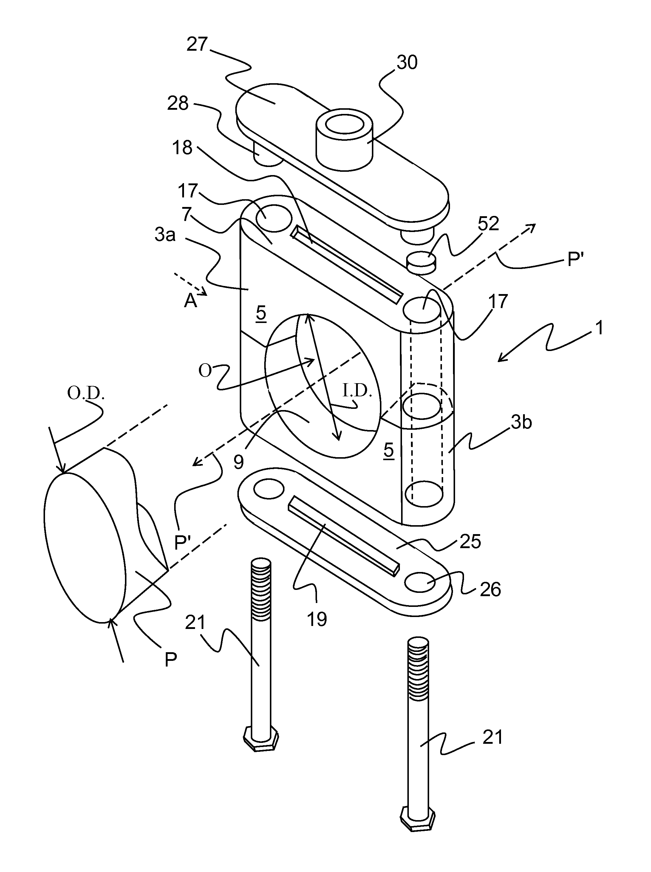
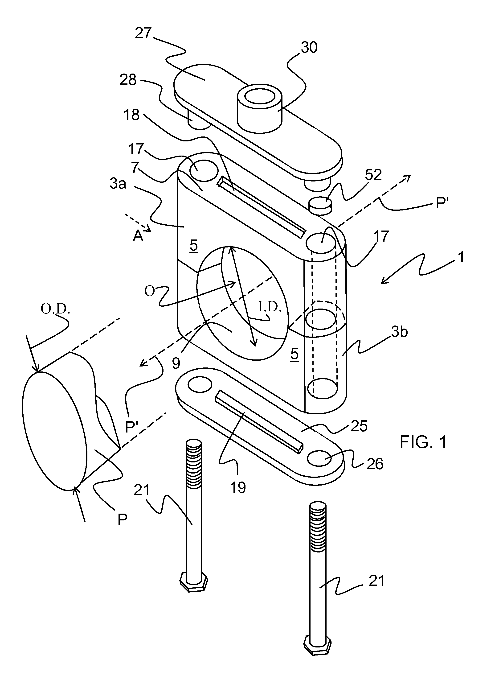
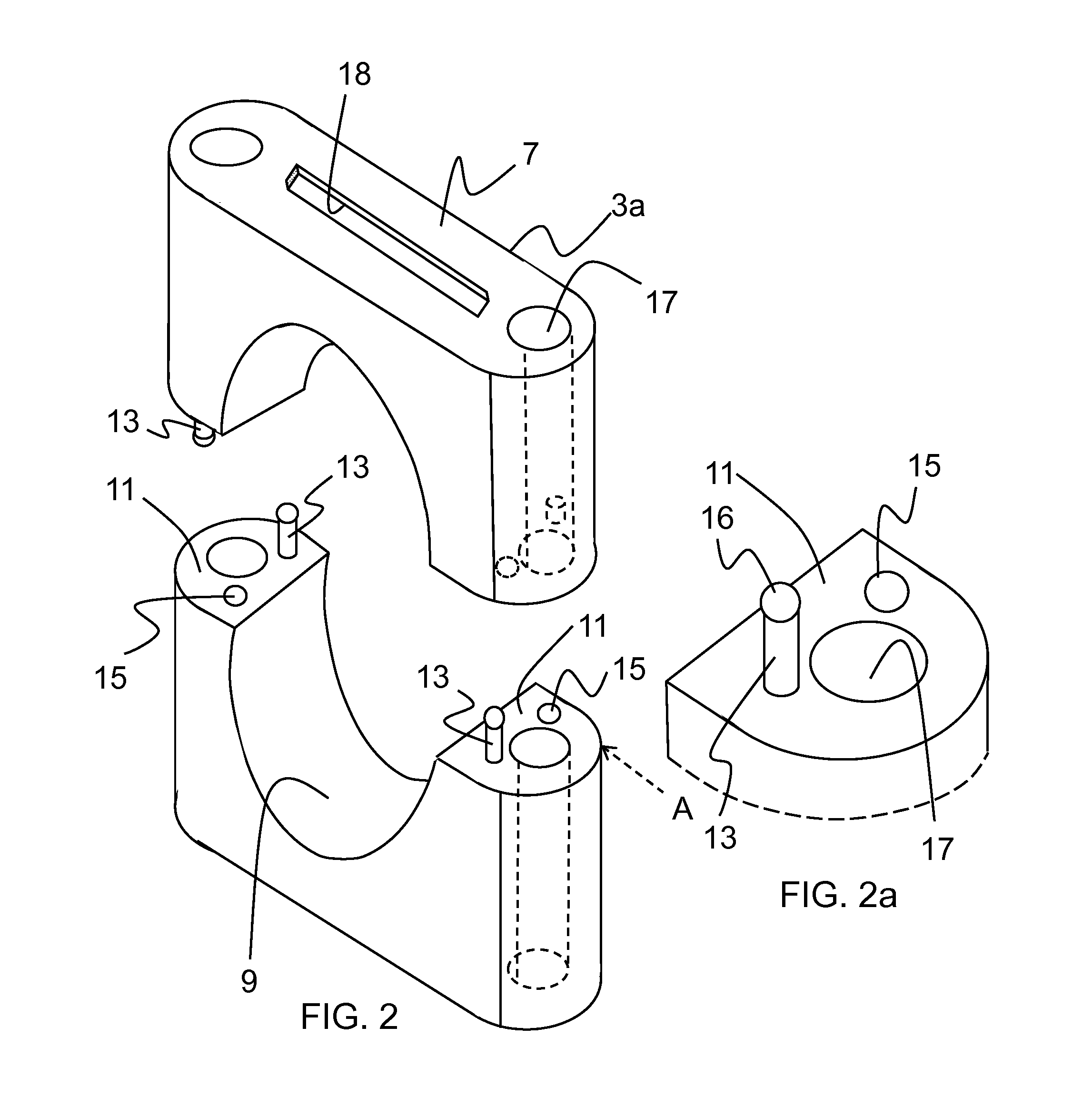
[0083]In general, the present invention relates to a block style pipe and tube support including a grommet block 1 as shown in FIG. 1. The block 1 consists of two attached and substantially identical upper and lower grommets 3 defining a pipe passage O having an inner diameter (I.D.) through which a pipe, tube or conduit P having an outer diameter (O.D.) can pass. The two grommets 3 are attachable, and also separable, along a grommet separation plane A. The O.D. of the pipe can be accommodated by a range of I.D.'s of the grommet block depending on how secure the pipe is to be supported and held by the support. The tighter the tolerance of the pipe O.D. and the grommet block I.D. the more securely the pipe is held and the greater reduction in vibration of the pipe. It is to be appreciated that with a larger tolerance the pipe is more inclined, or permitted, to move or slide axially generally along a pipe axis P′ in the pipe passage O. The grommets 3a, 3b can be modified to allow for ...


PUM

PropertyMeasurementUnit
Angleaaaaaaaaaa
Lengthaaaaaaaaaa
Forceaaaaaaaaaa

Abstract

A plastic, polymeric or silicone grommet used as a dampener or insulator for round and / or hex style tube, pipe and conduit hangers, and particularly to a grommet having a channel portion and a rounded edge portion which directly surrounds the edges of hanger brackets used as pipe supports. Each flat surface of the grommet is substantially rounded to prevent the collection of liquids, dirt or debris.

Description

[0001]This application is a Continuation-In-Part Application and claims the benefit of prior U.S. patent application Ser. No. 12 / 481,016 filed Jun. 9, 2009 and entitled Attachable Grommets for Hanging Pipes, which is now U.S. Publication No. US-2010-0308183 published Dec. 9, 2010 and U.S. patent application Ser. No. 12 / 815,738 filed Jun. 15, 2010 and entitled Attachable Grommets for Hanging Pipes, which is now U.S. Publication No. US-2010-0308184 published Dec. 9, 2010 all of which are hereby incorporated by reference in their entirety.FIELD OF THE INVENTION[0002]The present invention relates to block, round, or hex style tube and pipe hangers which include plastic or silicone grommets that are used as a dampener or insulator for hanging tubes and pipes and particularly to a post and port arrangement for securing and aligning the polymeric grommets during initial mounting and placement. The grommets are typically two opposing symmetrical parts that together define a passage having a...

Claims


Application Information

Patent Timeline
IPC IPC(8): F16L3/10B23P11/00
CPCF16L3/1091F16L3/222Y10T29/49826F16L55/035F16L3/1016F16L3/1075
Inventor HENNON, JOHN
Owner SYNTIRO DYNAMICS
Learn More