
Solar Cell Assembly with an Improved Photocurrent Collection Efficiency

a solar cell and photocurrent collection technology, applied in the field of solar cell assembly, can solve the problems of reducing affecting the stability of the solar cell against the temperature, and achieve the effect of improving the photocurrent collection efficiency

Inactive Publication Date: 2012-08-30
INST NUCLEAR ENERGY RES ROCAEC
View PDF10 Cites 7 Cited by
  • Summary
  • Abstract
  • Description
  • Claims
  • Application Information

AI Technical Summary

Benefits of technology

[0019]It is the primary objective of the present invention to provide a solar cell assembly with an improved photocurrent collection efficiency.

Problems solved by technology

However, most of the photocurrent is generated along the path c. Therefore, it is an important issue to reduce the surface recombination along the path c to increase the carrier-collection efficiency in a light-concentrating solar cell.
However, there are concerns about the sulfur passivation of the upper surface of the window layer as follows:1. There might be side reactions of the (NH4)2Sx solution with the other layers of the solar cell; and2. The stability of the solar cell against the temperature might be affected.
Regarding the above-mentioned documents, no matter the window layer is made of a lattice-matched or lattice-mismatched material, or an oxide layer is provided on the window layer, there are still oxygen-related defects on the upper surface of the window layer that reduce the photocurrent collection efficiency.

Method used


Image

  • Solar Cell Assembly with an Improved Photocurrent Collection Efficiency
  • Solar Cell Assembly with an Improved Photocurrent Collection Efficiency
  • Solar Cell Assembly with an Improved Photocurrent Collection Efficiency

Examples


Embodiment Construction

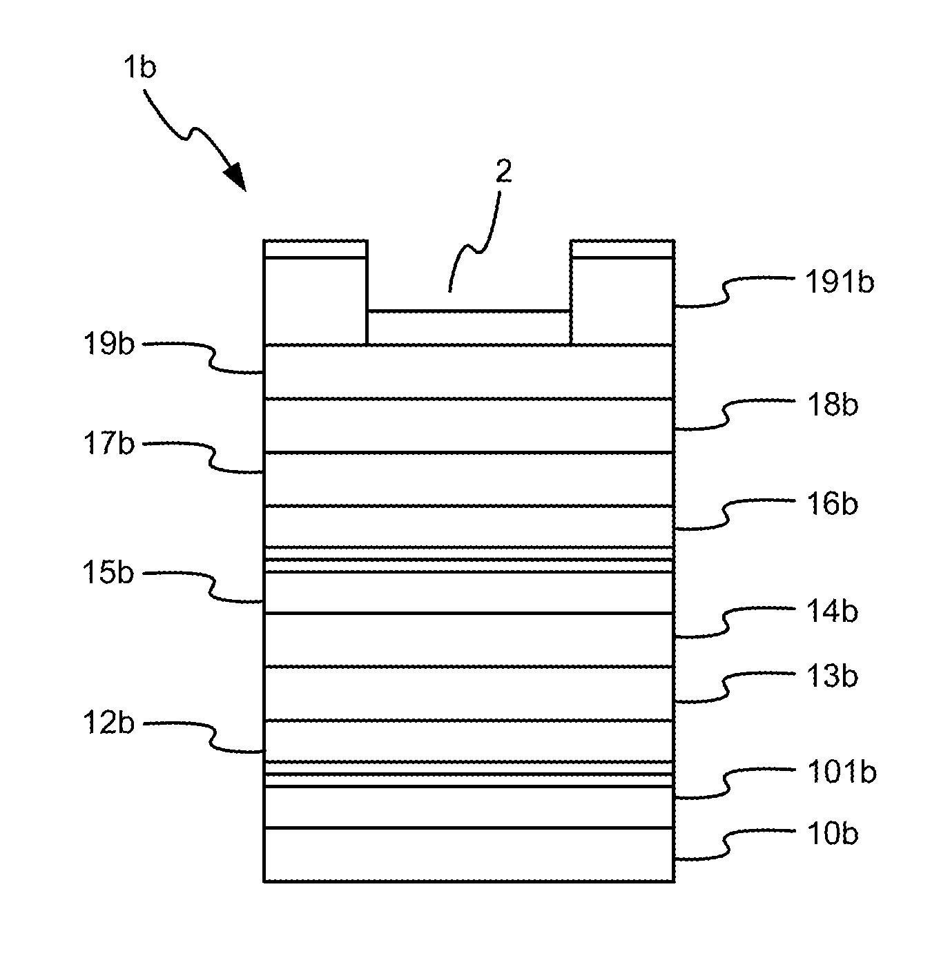
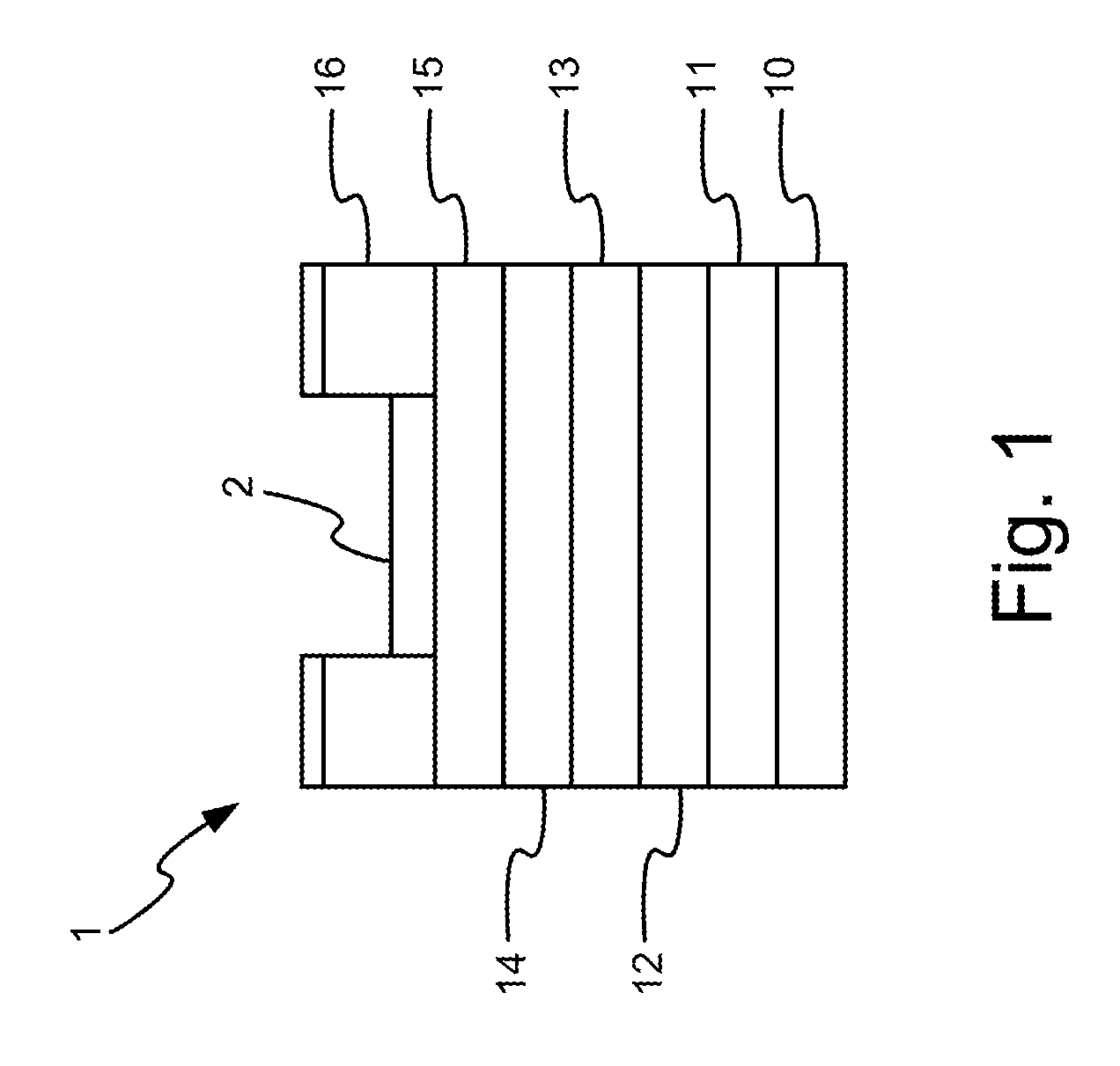
[0038]Referring to FIG. 1, there is shown a solar cell assembly with excellent photocurrent collection efficiency according to the first embodiment of the present invention. The solar cell assembly includes a solar cell 1 and a surface barrier layer 2.

[0039]The solar cell 1 includes at least one substrate 10, a buffer layer 11 provided on the substrate 10, a back surface field layer 12 provided on the buffer layer 11, a base layer 13 provided on the back surface field layer 12, an emitter layer 14 provided on the base layer 13, a window layer 15 provided on the emitter layer 14, and a contact layer 16 provided on the window layer 15. The solar cell 1 is a single-junction solar cell.

[0040]The surface barrier layer 2 is provided on the window layer 15. The surface barrier layer 2 is made of phosphide or arsenide.

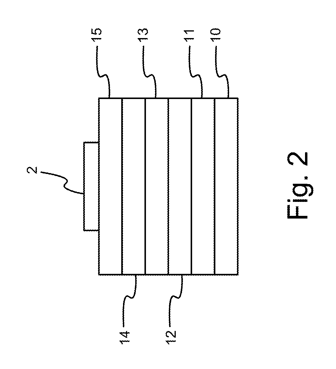
[0041]The production of the solar cell assembly will be described referring to FIGS. 2 and 3. At first, the surface barrier layer 2 is provided on the window layer 15 in a lit...


PUM


Abstract

Disclosed is a solar cell assembly with excellent photocurrent collection efficiency. The solar cell assembly includes a solar cell and a surface barrier layer. The solar cell includes a window layer. The surface barrier layer is provided on the window layer. The surface barrier layer is made of phosphide or arsenide.

Description

BACKGROUND OF INVENTION[0001]1. Field of Invention[0002]The present invention relates to a solar cell assembly and, more particularly, to a solar cell assembly with an improved photocurrent collection efficiency.[0003]2. Related Prior Art[0004]Referring to FIG. 7, a conventional solar cell 3 includes a substrate 31, a back surface field layer 32, a base layer 33, an emitter layer 34, a window layer 35 and a contact layer 36. The window layer 35 reduces surface recombination loss of photocurrent near the surface of the emitter layer 34 and hence increases the carrier-collection efficiency.[0005]From paths a, b and c for transmitting and collecting the photocurrent generated by the solar cell 3 irradiated by sun light, it can be found that the window layer 35 reduces the recombination of the photocurrent near the surface of the emitter layer 34 but it does not avoid the recombination loss of the photocurrent near the surface thereof, particularly in a light-concentrating condition. Ta...

Claims


Application Information

Patent Timeline
Patent Type & Authority Applications(United States)
IPC IPC(8): H01L31/0216H01L31/06
CPCH01L31/0693Y02E10/544H01L31/02167H01L31/0735
Inventor TSAI, YU-LIWU, CHIH-HUNG
Owner INST NUCLEAR ENERGY RES ROCAEC
Learn More