Polarization sensitive front projection screen

a technology of front projection and polarization, applied in the field of front projection system screens, can solve the problems of affecting the performance of the screen,

Inactive Publication Date: 2012-08-23
3M INNOVATIVE PROPERTIES CO
View PDF11 Cites 17 Cited by
  • Summary
  • Abstract
  • Description
  • Claims
  • Application Information

AI Technical Summary

Benefits of technology

[0010]An embodiment is a front projection system, comprising: a projector for projecting light to a screen, the light having a first polarization state; a screen for receiving the light from the projector and reflecting light to a viewer, the screen comprising: an absorber; and a film disposed adjacent the absorber, between the absorber and the projector, the film having: a high pow

Problems solved by technology

The light reflected from the wall was largely specularly reflected, with too much light contained in the specular reflection, and not enough light scattered into other reflected angles.
Even as the screens have evolved over the years, many screens still suffer degradation in performance due to ambient light.
This “non-image” light ap

Method used


Image

  • Polarization sensitive front projection screen
  • Polarization sensitive front projection screen
  • Polarization sensitive front projection screen

Examples


Embodiment Construction

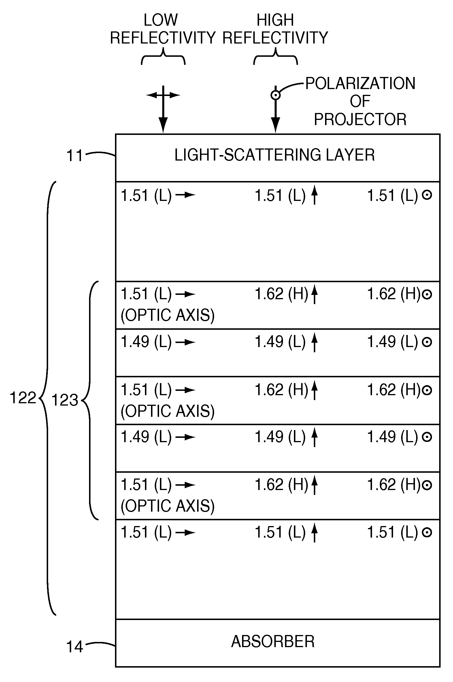
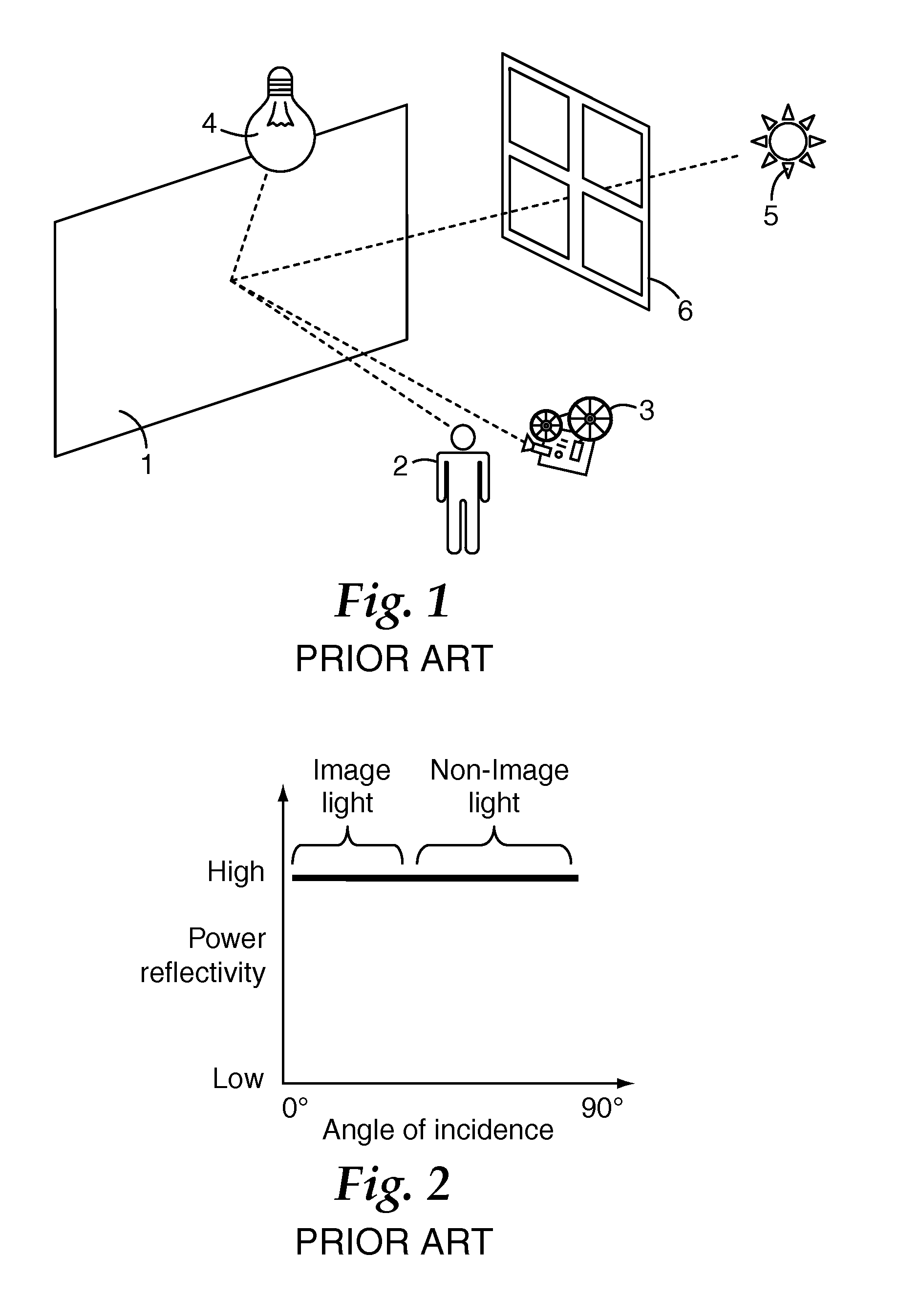
[0035]There exists a need for a front-projection screen that has a reduced sensitivity to ambient light. Such a screen is shown in generalized form in FIGS. 3-5, then in more detail in the figures and text that follow.

[0036]It is instructive to briefly review the inner workings of a typical modern projector. This description of the projector is merely exemplary, and should not be construed as limiting in any way.

[0037]In one type of projector, light from a source is collected by a condenser and directed onto a pixilated panel, such as a liquid crystal on silicon (LCOS) panel. The light reflected from the pixilated panel is then imaged onto a distant screen by a projection lens. In this type of projection system, the pixilated panel is generally tiny, compared to the viewable image on the screen, and it is generally considered desirable to situate the source, the condenser, the pixilated panel, and the intervening optics (excluding the projection lens) in the smallest possible volume...


PUM


Abstract

A projection system is disclosed, in which a screen may have improved rejection of ambient light by having a high reflectivity at low angles of incidence for a polarization parallel to that of the projector, a low reflectivity at high angles of incidence for a polarization parallel to that of the projector, and a low reflectivity at both low and high angles of incidence for a polarization perpendicular to that of the projector. In some embodiments, for p-polarized light polarized parallel to the projector, the power reflectivity is high at low angles of incidence and decreases to a low value at high angles of incidence. In some embodiments, for p-polarized light polarized perpendicular to the projector, the power reflectivity is low at low angles of incidence. In some embodiments, for s-polarized light polarized perpendicular to the projector, the power reflectivity remains low at all angles of incidence. In some embodiments, the screen includes a thin film structure that has alternating quarter-wave layers of isotropic and birefringent materials, which are refractive-index-matched for light polarized perpendicular to the projector, which form a high reflector at normal incidence for light polarized parallel to the projector, and which exhibit Brewster's angle effects for p-polarized light polarized parallel to the projector at high angles of incidence. The Brewster's angle effect may be reached by use of a light-scattering layer that increases the effective incident refractive index.

Description

FIELD OF THE INVENTION[0001]The present invention is directed to a screen for front projection systems.BACKGROUND[0002]Front projection systems have been around since the 1800s, in which an image is projected onto a screen, and the viewer sees the light reflected from the screen.[0003]Typical front projectors have evolved from theatrical film projectors, home movie projectors, education filmstrip projectors, slide projectors and overhead transparency projectors, through today's LCD-based projectors, with many variations along the evolutional path.[0004]The screens that accompany these projectors have also evolved over time. Presumably, the first projectors were projected onto a wall. The light reflected from the wall was largely specularly reflected, with too much light contained in the specular reflection, and not enough light scattered into other reflected angles. Early screens were an improvement over merely projecting onto the wall; in that a dedicated screen could incorporate a...

Claims


Application Information

Patent Timeline
IPC IPC(8): G03B21/60
CPCG03B21/604
Inventor WEBER, MICHAEL F.LIU, YUFENGNEVITT, TIMOTHY J.
Owner 3M INNOVATIVE PROPERTIES CO
Why Eureka
Try Eureka