
Matting agent coating device and inkjet recording device

a technology of coating device and coating agent, which is applied in the direction of coatings, printing, other printing devices, etc., can solve the problems of blocking, damage, and damage of printed matter, and achieve the effect of improving the blocking performance of stackers and stable metering accuracy

Inactive Publication Date: 2012-08-23
FUJIFILM CORP
View PDF7 Cites 16 Cited by
  • Summary
  • Abstract
  • Description
  • Claims
  • Application Information

AI Technical Summary

Benefits of technology

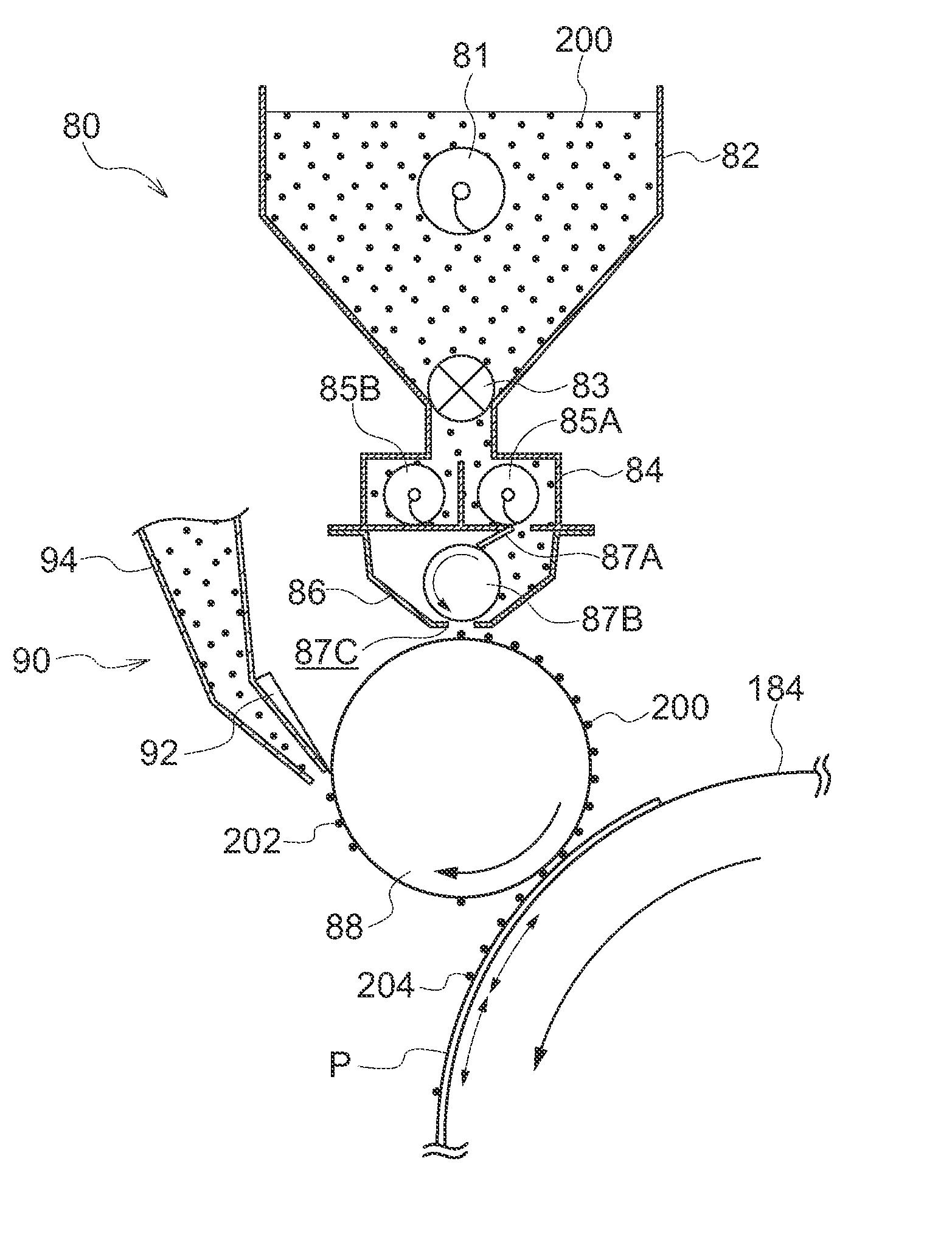
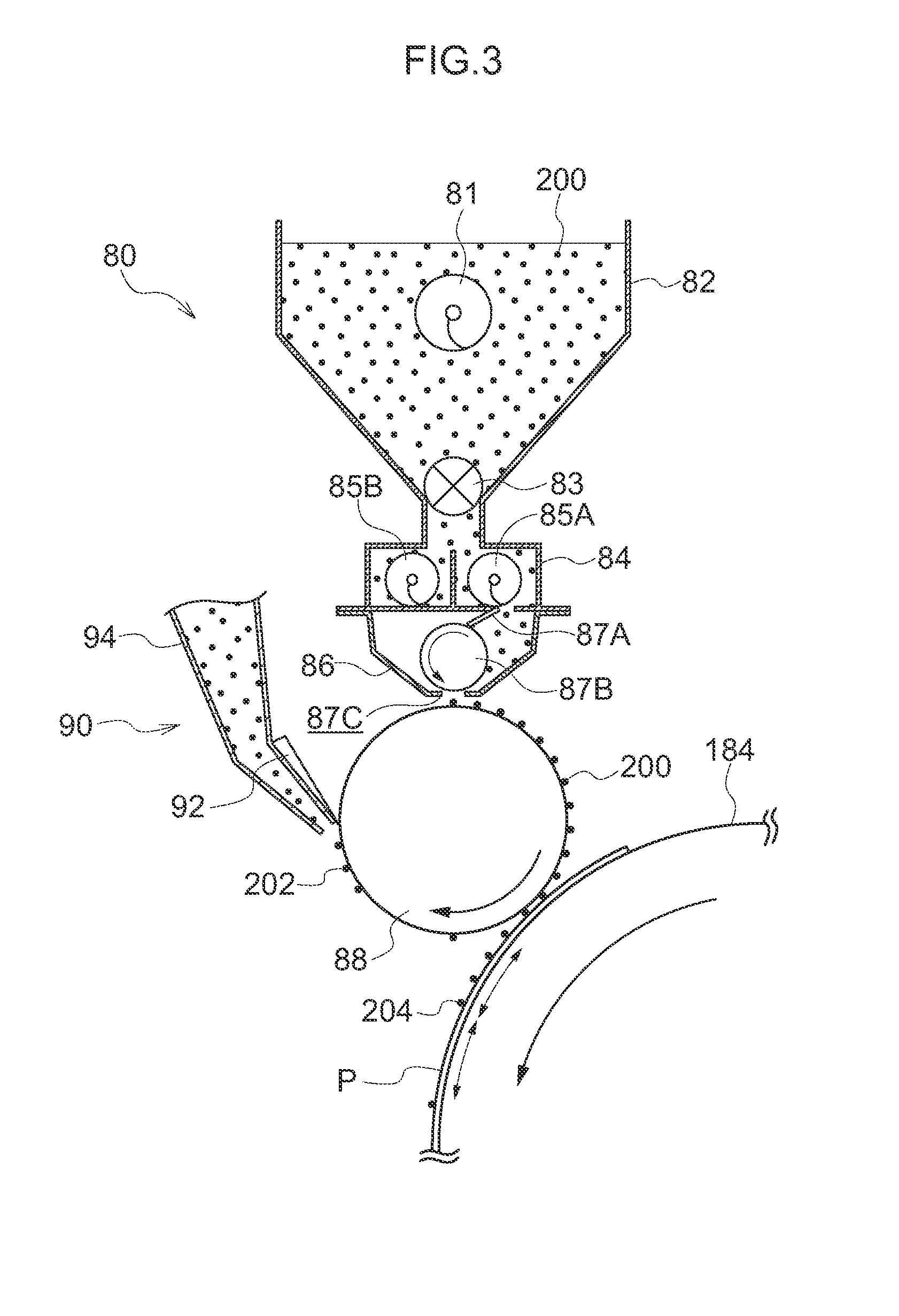
[0015]In accordance with the above-described structure, a matting agent that improves the stacker blocking performance is metered at the surface of the closed-cell rubber roller, and is applied to a recording medium surface by pressing by the application roller. Due thereto, dirtying of the device interior and the recording medium by the matting agent is prevented, and the matting agent can be applied onto the recording medium surface with stable metering accuracy.
[0019]In accordance with the above-described structure, due to the outer peripheral surface being covered by a PFA film, the application roller can be made to be highly stable while the surface smoothness and surface energy are maintained within desired ranges.
[0021]In accordance with the above-described structure, poor filling of the matting agent due to the pore size being too small can be prevented, and dropping-out of the matting agent due to insufficient holding force caused by the pore size being too large can be prevented.
[0023]In accordance with the above-described structure, the matting agent, that has not been applied from the application roller onto the recording medium surface, is recovered and re-used, and, at the same time, dirtying of the device interior can be prevented.
[0025]In accordance with the above-described invention, a matting agent that improves the stacker blocking performance is metered at the surface of the closed-cell rubber roller, and is applied to a recording medium surface by pressing by the application roller. Due thereto, dirtying of the device interior and the recording medium by the matting agent is prevented, and the matting agent can be applied onto the recording medium surface with stable metering accuracy.

Problems solved by technology

Conventionally, inkjet printers have had the problem that printed matter, for which processing is completed, are damaged due to a phenomenon known as blocking in which inks on stacked printed matter adhere (bond) to one another due to insufficient drying and insufficient fixing of the image portions.
In high-mass-production inkjet printers in particular, because there is the tendency for the drying and fixing time to be short, it is easy for insufficient drying and insufficient fixing to occur, and further, it is easy for blocking to arise when carrying out printing on thick paper.
However, with a powder spraying method, the problem arises that the printer interior is dirtied due to diffusion of excess powder, and, when carrying out double-sided printing, due to powder that has been supplied to printed matter dropping-off at the time of printing the reverse surface.
In particular, in an inkjet printer of a type that carries out printing by coating a pre-processing liquid onto the sheets, the powder spraying method may become problematic with respect to the points that the powder may become mixed into the pre-processing liquid coating section, or poor ejection may be caused due to the powder adhering to the inkjet heads.
However, although aforementioned Japanese Patent Application National Publication No. 2002-500974 discloses a measure for preventing diffusion of excess powder by an air curtain, there is the problem that dirtying of the printer by the powder that drops-off from printed matter cannot be overcome.
Further, if the structure disclosed in JP-A No. 8-224978 is applied to an inkjet printer in which it is easy for insufficient drying of a dispersion liquid, in which a matting agent is dispersed, and insufficient fixing to occur, there is the problem that there is the concern that blocking will occur more easily.

Method used


Image

  • Matting agent coating device and inkjet recording device
  • Matting agent coating device and inkjet recording device
  • Matting agent coating device and inkjet recording device

Examples


Embodiment Construction

[0031]Examples of exemplary embodiments relating to the present invention are described hereinafter with reference to the drawings.

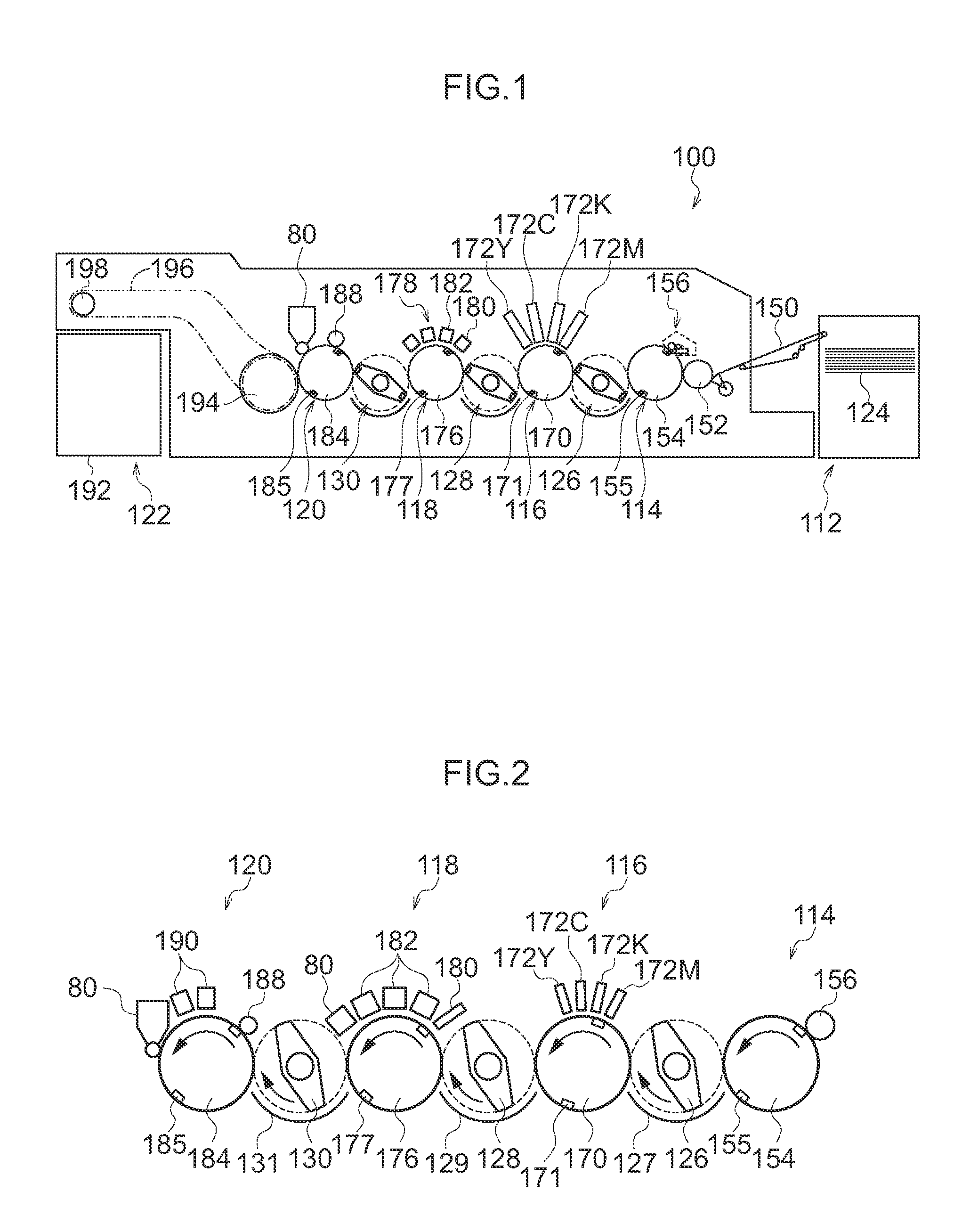
[0032]FIG. 1 is a schematic structural drawing showing the overall structure of an inkjet recording device relating to an exemplary embodiment of the present invention.

[0033]An inkjet recording device 100 is an impression-cylinder direct-drawing inkjet recording device that forms a desired color image by ejecting aqueous inks, that contain thermoplastic resin and color materials, of plural colors from inkjet heads 172M, 172K, 172C, 172Y, onto the recording surface of a recording medium P that is held at an impression cylinder (an image drawing drum 170) of an image drawing section 116. The inkjet recording device 100 is an on-demand type image forming device to which is applied a two-liquid reaction (agglomeration) method that carries out image formation on the recording medium P by, before ejecting ink, applying a processing liquid (containing an agglom...


PUM


Abstract

In a matting agent coating device, a matting agent within a supplying section is supplied to a metering section. A supplied amount of matting agent at a surface of a metering roller is metered by a metering blade, and an excess amount is filtered at a slit portion. Matting agent is supplied to an application roller that is provided directly beneath. For example, a closed-cell sponge rubber is used as a material of the metering roller, and a size of closed cells is around 5 to 100 times an average particle diameter of the matting agent. The matting agent that has been supplied to a surface of the application roller is transferred and applied onto a recording medium. The matting agent is transferred from the application roller onto image portions of the recording medium due to tackiness of an ink film forming an image.

Description

CROSS-REFERENCE TO RELATED APPLICATION[0001]This application claims priority under 35 USC 119 from Japanese Patent Application No. 2011-034933 filed on Feb. 21, 2011, the disclosure of which is incorporated by reference herein.BACKGROUND OF THE INVENTION[0002]1. Field of the Invention[0003]The present invention relates to a matting agent coating device and an inkjet recording device.[0004]2. Description of the Related Art[0005]Conventionally, inkjet printers have had the problem that printed matter, for which processing is completed, are damaged due to a phenomenon known as blocking in which inks on stacked printed matter adhere (bond) to one another due to insufficient drying and insufficient fixing of the image portions. In high-mass-production inkjet printers in particular, because there is the tendency for the drying and fixing time to be short, it is easy for insufficient drying and insufficient fixing to occur, and further, it is easy for blocking to arise when carrying out pr...

Claims


Application Information

Patent Timeline
IPC IPC(8): B41J2/01B05C11/00B05C1/00
CPCB41J2/0057B41J11/0015B41J2/01
Inventor FURUKAWA, KOJIIRITA, KIYOSHI
Owner FUJIFILM CORP
Learn More