
Systems and Methods for Ultrasound Imaging and Insonation of Microbubbles

a microbubble and ultrasound imaging technology, applied in the field of systems and methods for ultrasound imaging and microbubble insonation, can solve the problems of no non-invasive, clinically approved technique to assess the extent and location of such vascular pathologies, and increase the risk of premature death

Active Publication Date: 2012-08-16
UNIV OF VIRGINIA ALUMNI PATENTS FOUND
View PDF4 Cites 62 Cited by
  • Summary
  • Abstract
  • Description
  • Claims
  • Application Information

AI Technical Summary

Benefits of technology

[0094]In another aspect of the present invention, a method of assessing a treatment site of tissue of a subject to be treated is provided, including: advancing a catheter invasively into a subject, so that a distal end portion of the catheter is placed at or in proximity to the treatment site; dispensing the microbubbles from the catheter in a manner that the microbubbles flow over the treatment site, wherein the microbubbles comprise molecular targeted, drug charged microbubbles that selectively adhere to the tissue to be treated, based on at least one molecular marker; allowing the microbubbles to accumulate on the treatment site for a predetermined time commencing from beginning of the dispensing, and after passage of the predetermined time, viewing the treatment site to examine the size of the area of the treatment site.

Problems solved by technology

The above cited recent studies indicate that there is a significant, growing population (approximately 6 Million individuals worldwide [4]) who currently find themselves having been implanted with DES and face a choice between taking the expensive and risky drug clopidogrel—potentially for life—or increased risk of premature death.
However, there is currently no non-invasive, clinically approved technique to assess the extent and location of such vascular pathologies.

Method used


Image

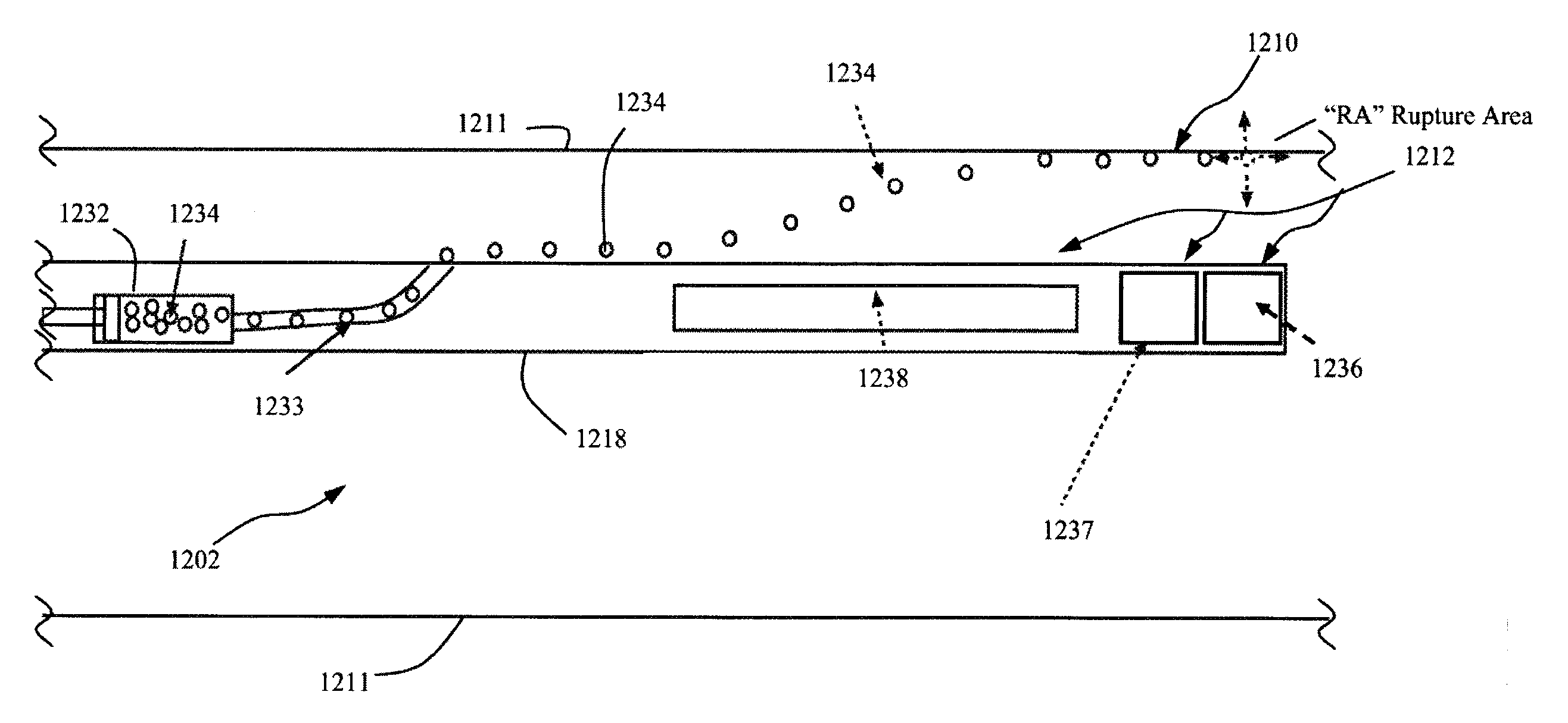
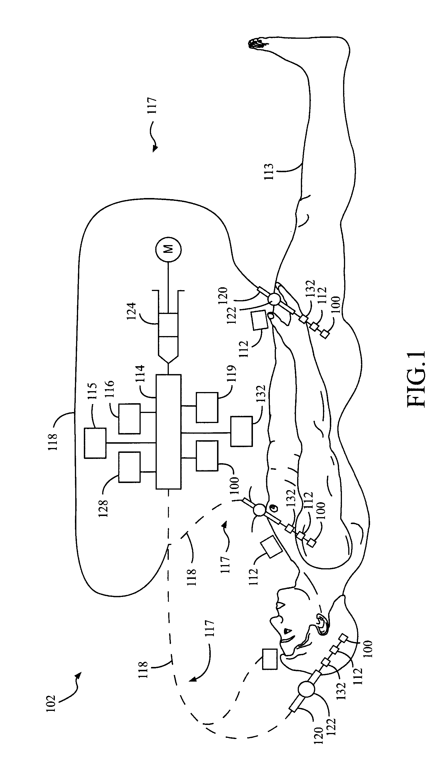
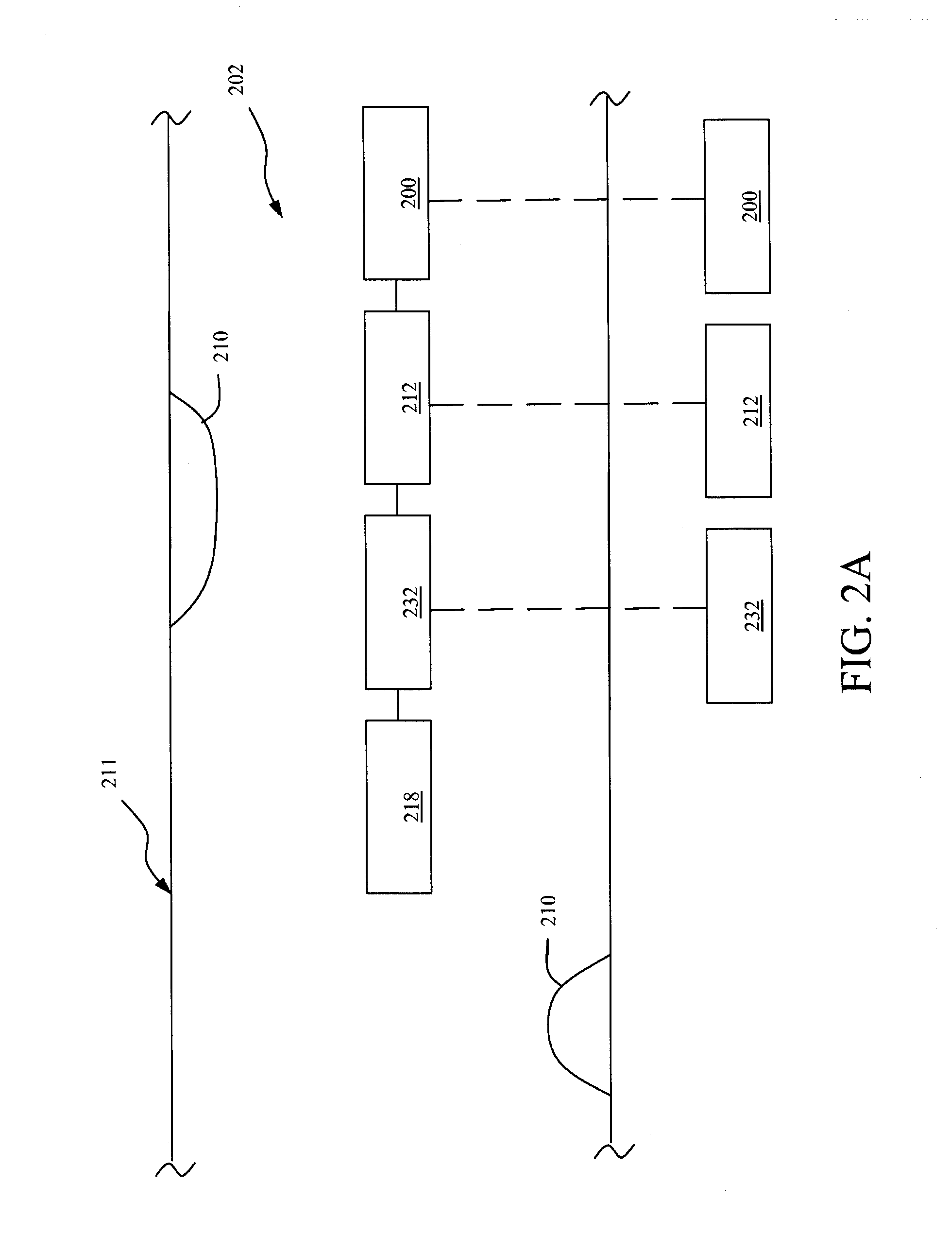
  • Systems and Methods for Ultrasound Imaging and Insonation of Microbubbles
  • Systems and Methods for Ultrasound Imaging and Insonation of Microbubbles
  • Systems and Methods for Ultrasound Imaging and Insonation of Microbubbles

Examples


example

[0405]The following example is put forth so as to provide those of ordinary skill in the art with a complete disclosure and description of how to make and use the present invention, and is not intended to limit the scope of what the inventors regard as their invention nor is it intended to represent that the experiment below is all or the only experiment performed. Efforts have been made to ensure accuracy with respect to numbers used (e.g. amounts, temperature, etc.) but some experimental errors and deviations should be accounted for. Unless indicated otherwise, parts are parts by weight, molecular weight is weight average molecular weight, temperature is in degrees Centigrade, and pressure is at or near atmospheric.

[0406]A purpose of this study was to, among other things, determine whether an intravascular ultrasound catheter could mediate plasmid DNA transfection from microbubble carriers to the porcine coronary artery wall following balloon angioplasty.

[0407]An Atlantis SR Pro I...


PUM


Abstract

A catheter system including an elongate tubular member having a proximal end portion, a distal end portion and a lumen extending through at least a portion of a length of the elongate tubular member. The distal end portion of the elongate member is dimensioned and adapted to advance to or in proximity to a treatment site of a subject. A microbubble device is in fluid communication with the lumen. The microbubble device includes at least one input port for receiving a flow of material into the device and an output port configured to output microbubbles from the microbubble device. A second tubular member is in fluid communication with one of the at least one input ports. A pressure fitting arrangement is adapted to maintain a seal between the second tubular member and the input port.

Description

CROSS-REFERENCE[0001]This application claims the benefit of U.S. Provisional Application No. 61 / 227,284 filed Jul. 21, 2009 and titled “System for Treatment and Imaging Using Ultrasonic Energy and Microbubbles and Related Method Thereof, U.S. Provisional Application No. 61 / 253,435 filed Oct. 20, 2009 and titled “System for Treatment and Imaging Using Ultrasonic Energy and Microbubbles and Related Method Thereof, and U.S. Provisional Application No. 61 / 298,741 filed Jan. 27, 2010 and titled “System for Treatment and Imaging Using Ultrasonic Energy and Microbubbles and Related Method Thereof, each of which applications is incorporated herein, in its entirety, by reference thereto.GOVERNMENT RIGHTS[0002]This invention was made with government support under federal grant nos. R01 EB002185 and HL090700 awarded by the National Institutes of Health. The United States Government has certain rights in this invention.BACKGROUND OF THE INVENTION[0003]Cardiovascular disease (CVD) was blamed for...

Claims


Application Information

Patent Timeline
Patent Type & Authority Applications(United States)
IPC IPC(8): A61M37/00A61K49/22A61B8/00
CPCA61B8/543A61N2007/0039A61B6/503A61B2017/22054A61B2019/528A61N7/00A61B6/504A61B2017/22021A61B2017/00893A61B5/7285A61B8/481A61B17/22004A61B8/12A61N2007/0043A61B8/445A61M2025/1052A61M25/0082A61M37/0092A61B8/06A61B2017/22088A61B2019/5234A61B6/541A61B2017/22089A61B2017/22067A61M25/10A61M2025/0073A61B8/0891A61B17/2202A61B17/22A61B2090/3735A61B2090/3784A61M25/00A61M37/00
Inventor HOSSACK, JOHN A.WAMHOFF, BRIAN R.KLIBANOV, ALEXANDER L.CHEN, JOHNNYFRENCH, BRENT A.
Owner UNIV OF VIRGINIA ALUMNI PATENTS FOUND
Learn More