
Governor for a timepiece wheel set or strike wheel set

a technology of timepiece wheels and governors, which is applied in the direction of electromechanical clocks, sound producing devices, timers, etc., can solve the problems of requiring space for devices, affecting the user's comfort, and audible and unpleasant defects for users

Active Publication Date: 2012-08-16
MONTRES BREGUET
View PDF3 Cites 23 Cited by
  • Summary
  • Abstract
  • Description
  • Claims
  • Application Information

AI Technical Summary

Benefits of technology

[0020]The invention thus proposes to provide a new solution to the problem of racing, particularly suited to watches.
[0022]In an innovative manner, the invention solves this problem by integrating a mechanism that uses energy. Therefore, the invention concerns a regulating device for a timepiece striking mechanism, which is arranged to regulate power consumption to a level that is exactly right for the striking mechanism, and which includes energy dissipating means for this purpose.

Problems solved by technology

Indeed, any defect is audible and unpleasant for the user, especially if the timepiece is an expensive one.
The consequences are detrimental, in particular as regards the nature of the following striking sequence, which may be incorrect.
These devices require space and cannot be properly integrated in watches.
They are often difficult to make, imprecise as regards speed, and very often noisy, which is unacceptable for an expensive musical or grand strike timepiece.
Any regulation of this speed, when it exists, is conventionally achieved with a lever system or with a mechanical governor with inertia blocks such as that disclosed in CH Patent No. 34 in the name of Barbezat-Baillot, which use a good deal of energy and may be bulky.
Known governors are imprecise, and cannot precisely limit angular speed deviation.
These shocks generate vibrations which are transmitted to the middle part, bezels and the crystal, which radiate in the air, like the chimes of the strike, with a noise that interferes with the sound of the chimes.
Further, these shock or friction based governors are difficult to make, imprecise as regards the regulated speed, and often noisy.
Consequently, in many cases, the chimes or music slow down at the end of the function, which is unpleasant for the user.
Known governors require a good deal of space and / or are noisy.

Method used


Image

  • Governor for a timepiece wheel set or strike wheel set
  • Governor for a timepiece wheel set or strike wheel set
  • Governor for a timepiece wheel set or strike wheel set

Examples


Embodiment Construction

[0060]The invention concerns the field of mechanical speed regulation for rotating assemblies.

[0061]The invention concerns in particular the field of horology, and more specifically that of timepieces including a striking mechanism, and will be more specifically described for this preferred application. However, the invention can be applied to pivoting speed regulation for any rotating assembly, whatever the scale thereof.

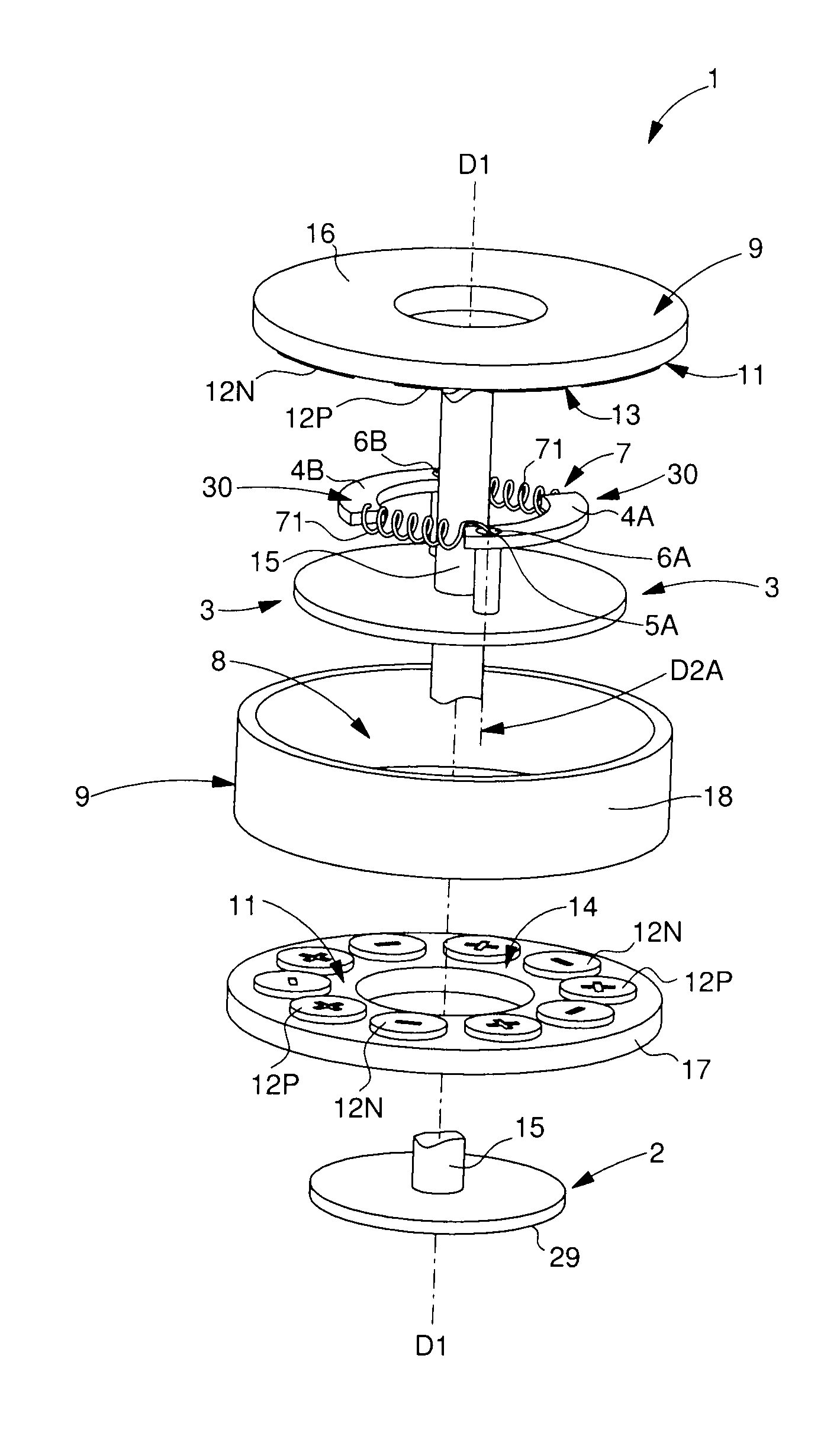
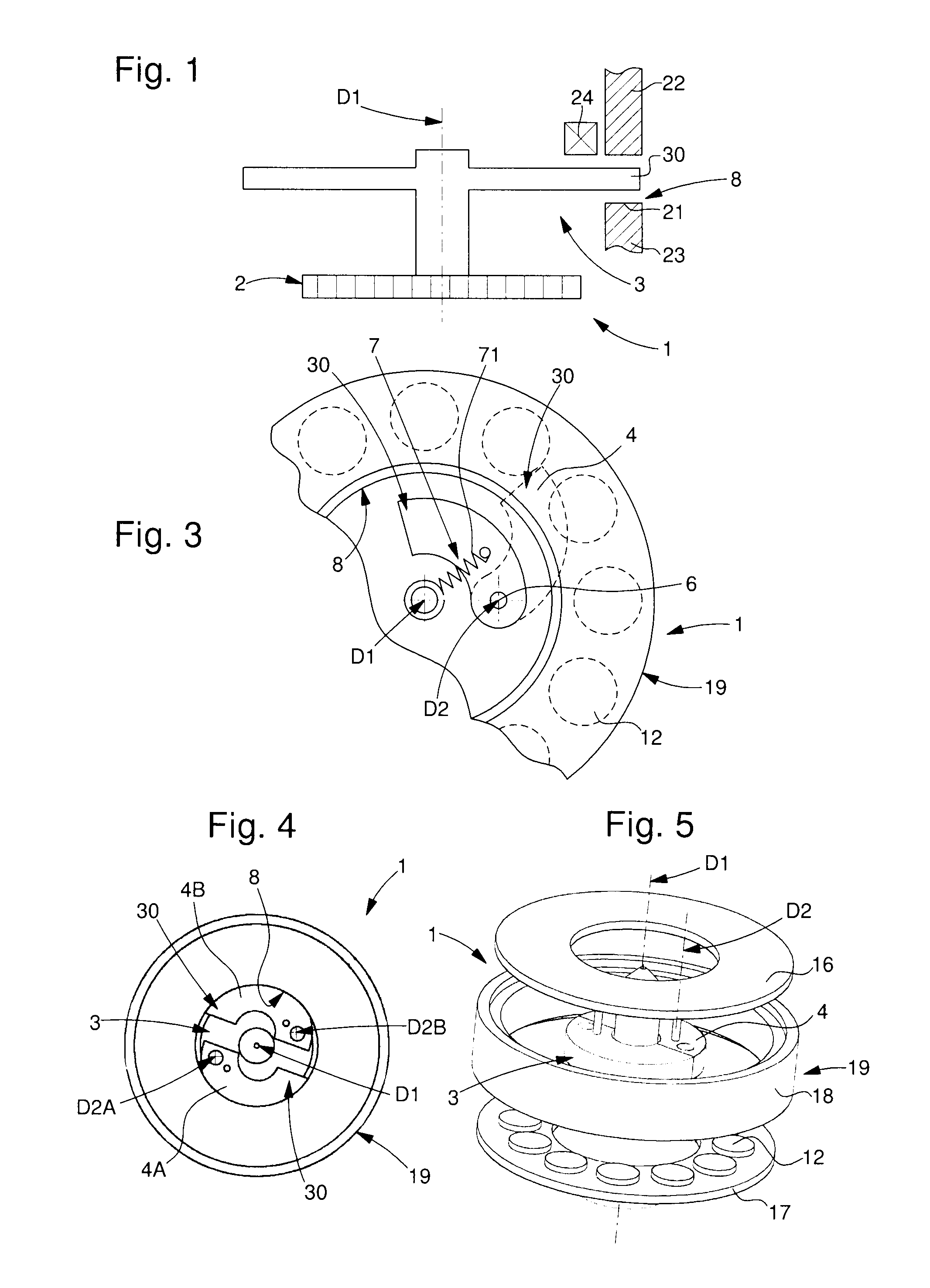
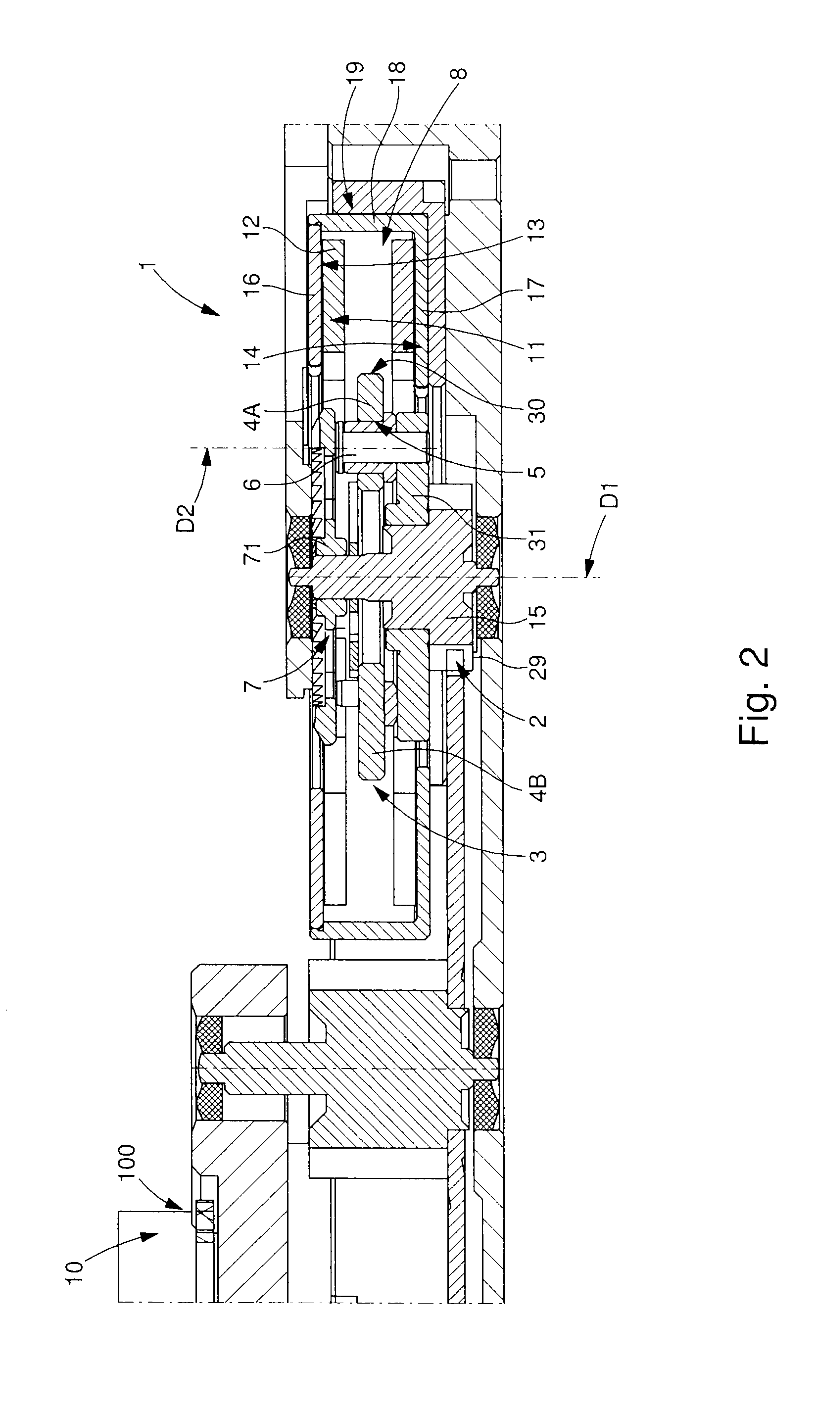
[0062]In this description of a preferred use of the invention, the invention concerns a regulating mechanism for a timepiece wheel set or strike wheel set 1, for a timepiece or musical box, which will be designated hereinafter by the generic term “timepiece”.

[0063]This governor for a timepiece wheel set or strike wheel set 1 is intended to regulate the operation of a mechanism, and in particular in the particular application set out in detail hereinafter and illustrated by the Figures, a musical or striking mechanism 10. A “timepiece wheel set or strike wheel set g...


PUM


Abstract

Timepiece wheel governor (1) for regulating the pivoting speed (ω) of a wheel set (3), about a pivot axis (D1), including a pivoting inertia-block (4).It includes a means (7) of returning said block (4) towards said axis (D1), and, when said wheel set (3) pivots at a lower speed than a reference speed (ωc), said block (4) remains confined within a first volume of revolution (VI), and, when said wheel set (3) pivots at a higher speed than said reference speed (ωc), said block (4) is engaged, in one peripheral portion (30) thereof, in a second volume (VE) contiguous with and external to said first one (VI), said peripheral portion (30) cooperating in said second volume (VE) with a regulating means arranged to brake said wheel set (3) and return the pivoting speed (ω) thereof to said reference speed (ωc), and to dissipate the surplus energy.

Description

[0001]This application claims priority from European Patent Application No. 11154181.9 filed Feb. 11, 2011, the entire disclosure of which is incorporated herein by reference.FIELD OF THE INVENTION[0002]The invention concerns a governor for a timepiece wheel set or strike wheel set, for regulating the pivoting speed of a wheel set about a first pivot axis, around a reference speed value, wherein said wheel set is driven, via transmission means, by an energy source delivering a mechanical torque, and said wheel set includes at least one inertia-block pivotally mounted about a primary pivot about a second pivot axis parallel to said first pivot axis and at a distance therefrom.[0003]The invention also concerns a spring comprising an inertia governor for regulating the pivoting speed of a wheel set about a first pivot axis, around a reference speed value, wherein said wheel set is driven, via transmission means, by an energy source delivering a variable torque at a variable angular spe...

Claims


Application Information

Patent Timeline
IPC IPC(8): G04B21/00G10F1/06
CPCG04B17/30G04B21/06G10F1/06G05D13/24G05D13/14G04B23/00G05D13/28G10F5/02G10K1/065
Inventor PITTET, JANBORN, JEAN-JACQUESCONUS, THIERRYGOELLER, ERICRAGOT, PATRICKMARECHAL, SYLVAINSARCHI, DAVIDEFAVRE, JEROME
Owner MONTRES BREGUET
Learn More