
Device for reducing speckle effect in a display system

a display system and speckle technology, applied in the field of speckle devices, can solve the problems of generating granular bright and dark patterns called speckles, giving rise to scattering, and more difficult in miniaturizing systems, and achieve the effect of suppressing speckle noise and simple optical systems

Inactive Publication Date: 2012-08-16
HONG KONG APPLIED SCI & TECH RES INST
View PDF2 Cites 29 Cited by
  • Summary
  • Abstract
  • Description
  • Claims
  • Application Information

AI Technical Summary

Benefits of technology

[0017]An object of the present invention is to provide a mirror and an illumination light source capable of effectively suppressing speckle noise using a simple optical system. The present invention provides a MEMS (microelectromechanical system) device which has a movable plate attached to a stationary frame. The movable plate has a region with features capable of scattering incident laser beams.
[0019]The MEMS device provided by the present invention can be manufactured in a batch fabrication process which lowers the device unit cost. The MEMS fabrication technology results in a small device form factor which is highly desirable in many portable consumer electronic products.
[0020]Furthermore, high optical efficiency can be achieved by using the MEMS device according to the present invention which works without any diffuser and the reflective surface profiles provided by the MEMS device of the present invention are more controllable.
[0021]Since no external moving actuator or diffuser is needed, the present invention has low power consumption.
[0022]The MEMS device according to the present invention allows a controllable vibration amplitude or frequency so that parameter tuning can be performed to attain an optimized laser de-speckle effect. The vibration amplitude is adjusted by, for example, varying input driving voltage to the MEMS device while the vibration frequency is tuned by designing the dimensions of the actuating parts of the MEMS device, for example, by changing torsional bar dimensions. The present invention provides a robust structure with a similar process flow to the MEMS scanning mirror fabrication, enabling further integration of the de-speckle device into the MEMS scanning mirror.
[0023]One aspect of the present invention is to provide a MEMS device for reducing speckle effect in a laser scanning projection display, which includes a movable plate rotatable along a first axis of rotation and further rotatable along a second axis of rotation, the first axis of rotation being substantially perpendicular to the second axis of rotation; one or more first actuators for moving the movable plate along at least a first direction; and one or more second actuators for moving the movable plate along at least a second direction. The first actuators and the second actuators are capable of moving the movable plate such that a combination of vertical, transverse and rotational motions of the movable plate reflecting a laser beam at distinct angles are possible using different regions of the movable plate temporally. The combination of motions in different directions makes the incident laser beam strikes on the scanning mirror at different angles forming a substantially circular locus of incident points.

Problems solved by technology

One type of noise is known to be speckles and this sort of speckle noise is particularly common for displays with a coherent light source such as a laser in a display, such as a HUD or a LSP display.
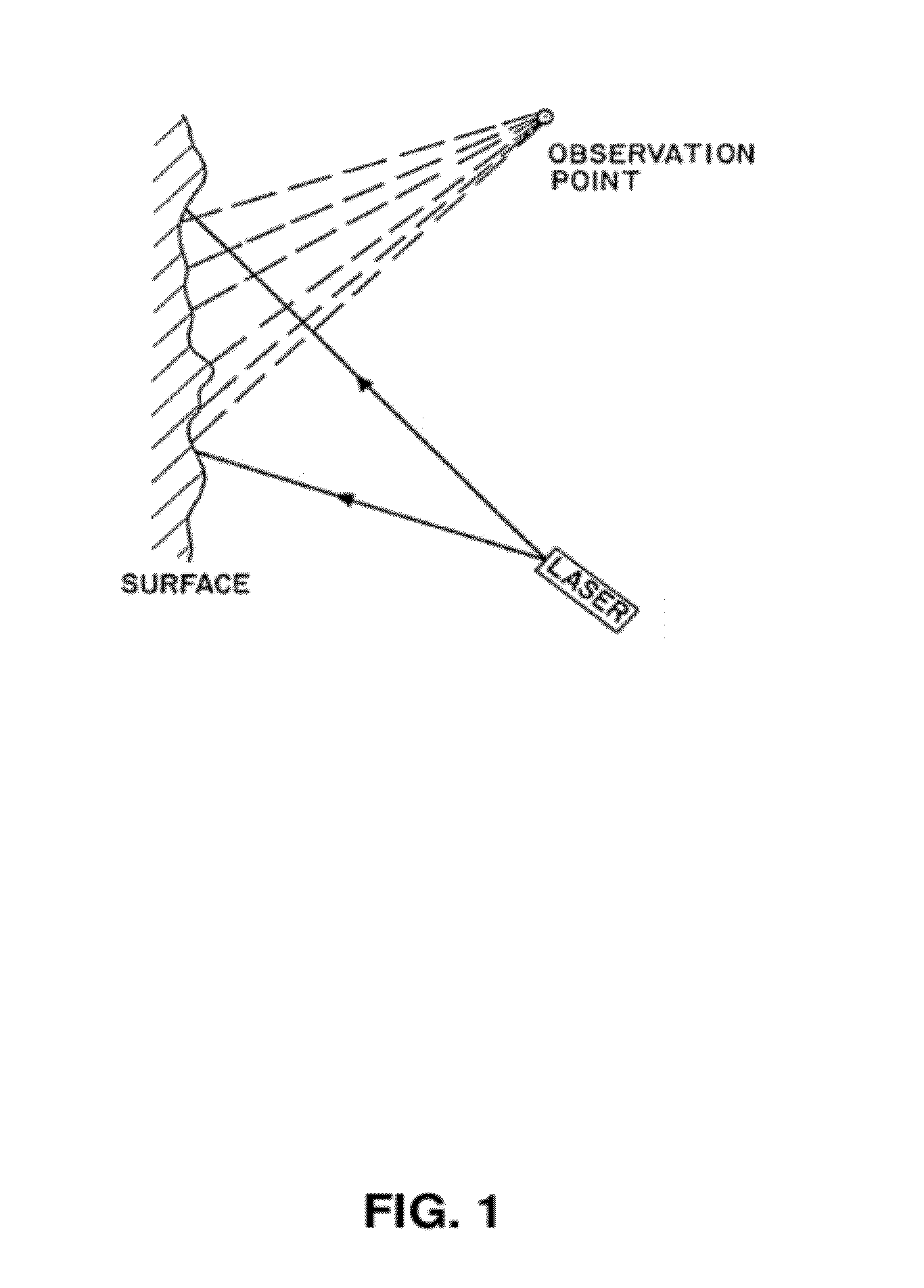
When compared with the wavelengths of visible light, the surface of any screen can be regarded as rough and therefore gives rise to scattering.
The reflected light rays reaching a viewer's eyes from various independent scattering areas on the screen surface have relative phase differences and interfere with one anther, generating granular bright and dark patterns called speckle.
Some requires an addition component like a diffuser to be provided in the system and may make it even more challenging in miniaturizing the systems, for example, a diffuser directing the diffused laser light to a rocking mirror for speckle reduction as described in the U.S. Pat. No. 4,155,630 titled “Speckle Elimination By Random Spatial Phase Modulation”, or a spinning diffuser as described in the U.S. Pat. No. 5,313,479 titled “Speckle-free Display System using Coherent Light”.
Use of additional components may further contribute to difficulties in integrating the speckle reduction scheme into existing systems, while some even require external moving actuators which lead to additional power consumption.
Some proposed solutions require a moving screen which not only makes image display impossible on any still screen but also may become problematic to find an appropriate means to move the screen as the screen size increases.
For example, it will be difficult for the transducer described in U.S. Pat. No. 5,272,473 entitled “Reduced-Speckle Display System” to work for a large screen where the transducer is required to be coupled to a display screen to set up surface acoustic waves which traverse the display screen.

Method used


Image

  • Device for reducing speckle effect in a display system
  • Device for reducing speckle effect in a display system
  • Device for reducing speckle effect in a display system

Examples


Embodiment Construction

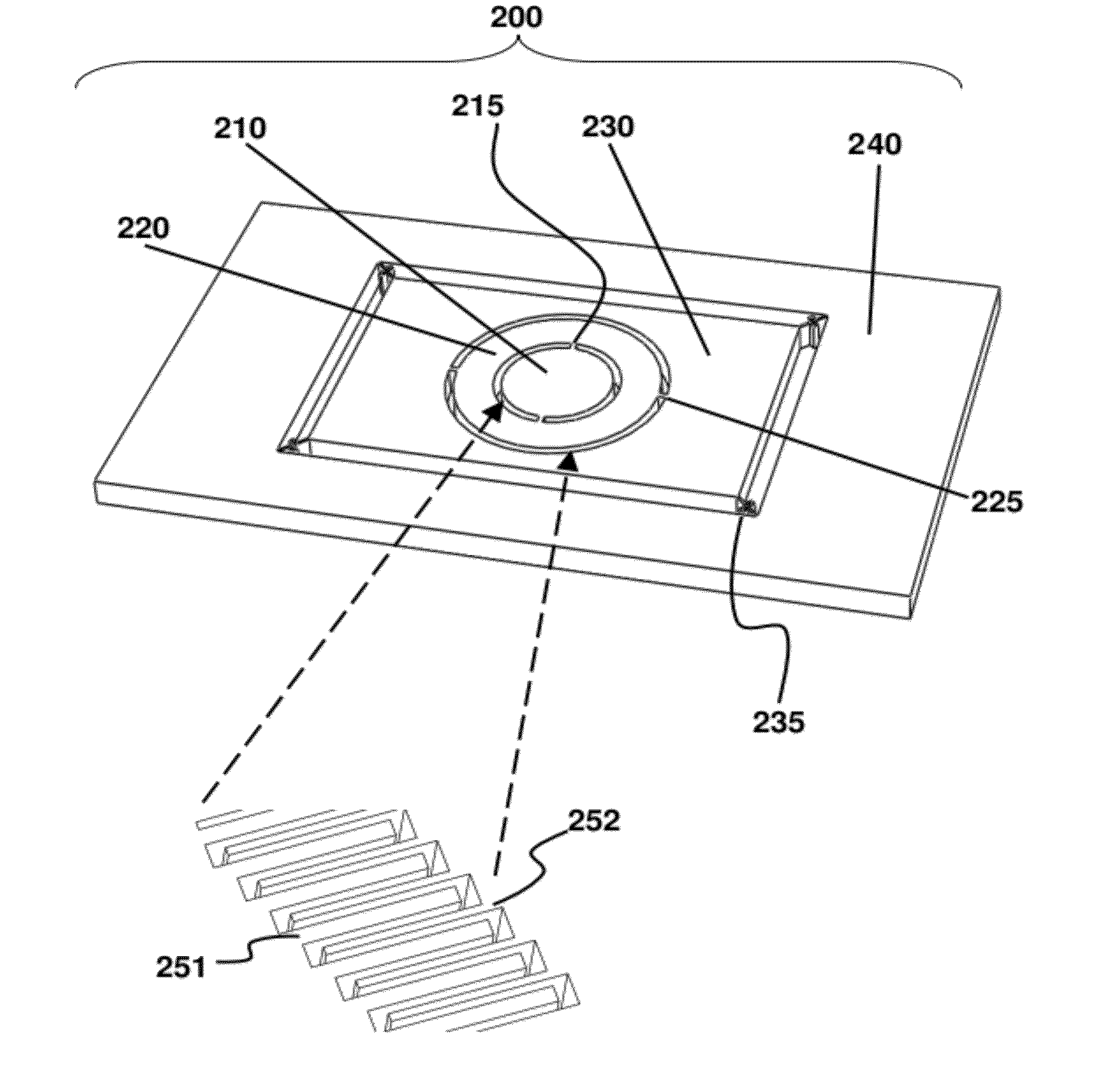
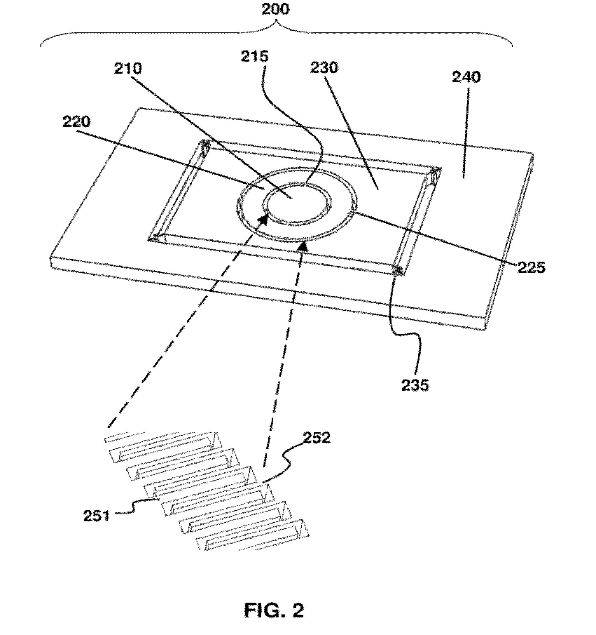
[0051]FIG. 2 depicts a laser de-speckle device 200 according to one embodiment of the present invention. The de-speckle device 200 includes movable plate 230 supported by supporting frame 240 via supporting springs 235. The supporting springs 235 can also be implemented as a torsional bar. Such torsional bars or supporting springs are designed with various dimensions to fit the oscillating frequency of the movable plate 230. Movable plate 230 is capable of vibrational motion in the plane of the movable plate and also in the direction perpendicular to the plane of the plate. The vibrational motion of movable plate 230 is periodic; thus light incident on any device supported by the movable plate will strike at different incident angles of the device according to the time of incidence. Consequently, an incident laser beam(s) will be reflected and / or scattered from a device supported by the movable plate with temporally varied properties, reducing the coherence. The reflected laser beam...


PUM


Abstract

The present invention relates to a method and apparatus for speckle noise reduction in laser scanning display. In particular, a MEMS device which can superpose vibrational motion onto a biaxial scanning mirror is provided for reducing the effect of speckling.

Description

CROSS REFERENCE TO RELATED PATENT APPLICATION[0001]All the subject matter of the co-pending U.S. patent application entitled “Device for Reducing Speckle Effect in a Display System” filed under the attorney docket number P3449US00 on 16 Feb. 2011 and the entire content thereof is hereby incorporated by reference.TECHNICAL FIELD[0002]The present application relates to an apparatus for projecting a digital image in general and, more particularly, to de-speckling devices and methods that can reduce or remove speckle in an image formed by a laser-based projector.BACKGROUND[0003]We receive visual information all the time, for example, watching movies. Nowadays, a huge amount of visual information is generated because of the user-friendliness of consumer electronics such as digital cameras. Similarly, there is a huge demand for displays from which we receive visual information. The development of display technology has been fast and the number of different ways to display an image has bee...

Claims


Application Information

Patent Timeline
IPC IPC(8): G02B26/10G02B27/48
CPCG02B26/0833G02B26/101G02B27/48B81B3/0062G02B5/0236G02B5/0284G02B5/021
Inventor CHAN, YICK CHUENLAM, SIU WAIFENG, YAO JUNLEE, FRANCIS CHEE-SHUENCHAN, HO YIN
Owner HONG KONG APPLIED SCI & TECH RES INST
Learn More