
Antenna device and communication device

Inactive Publication Date: 2012-08-16
DEXERIALS CORP
View PDF5 Cites 23 Cited by
  • Summary
  • Abstract
  • Description
  • Claims
  • Application Information

AI Technical Summary

Benefits of technology

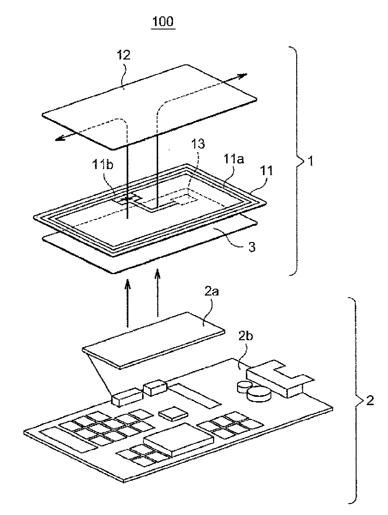
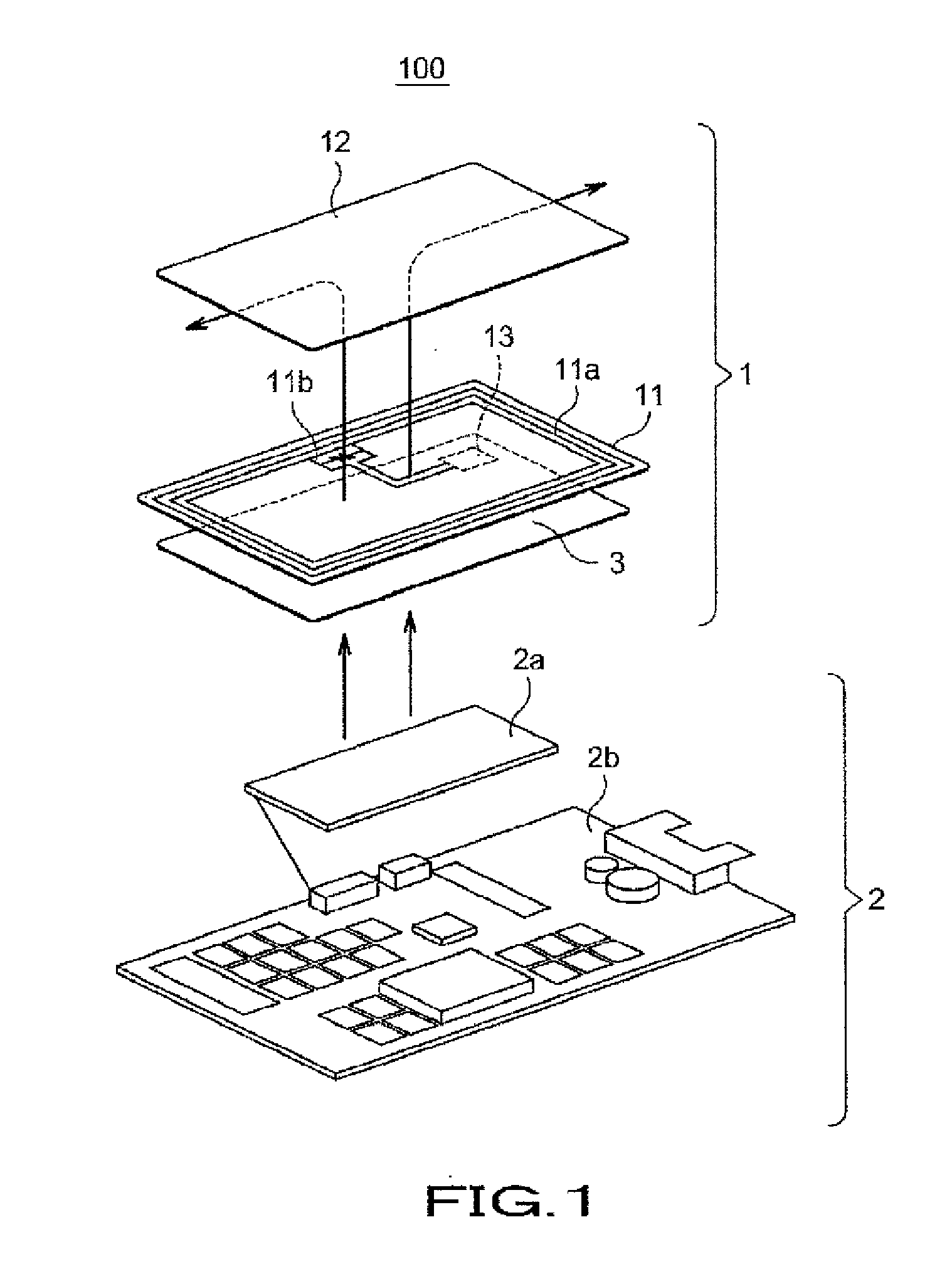
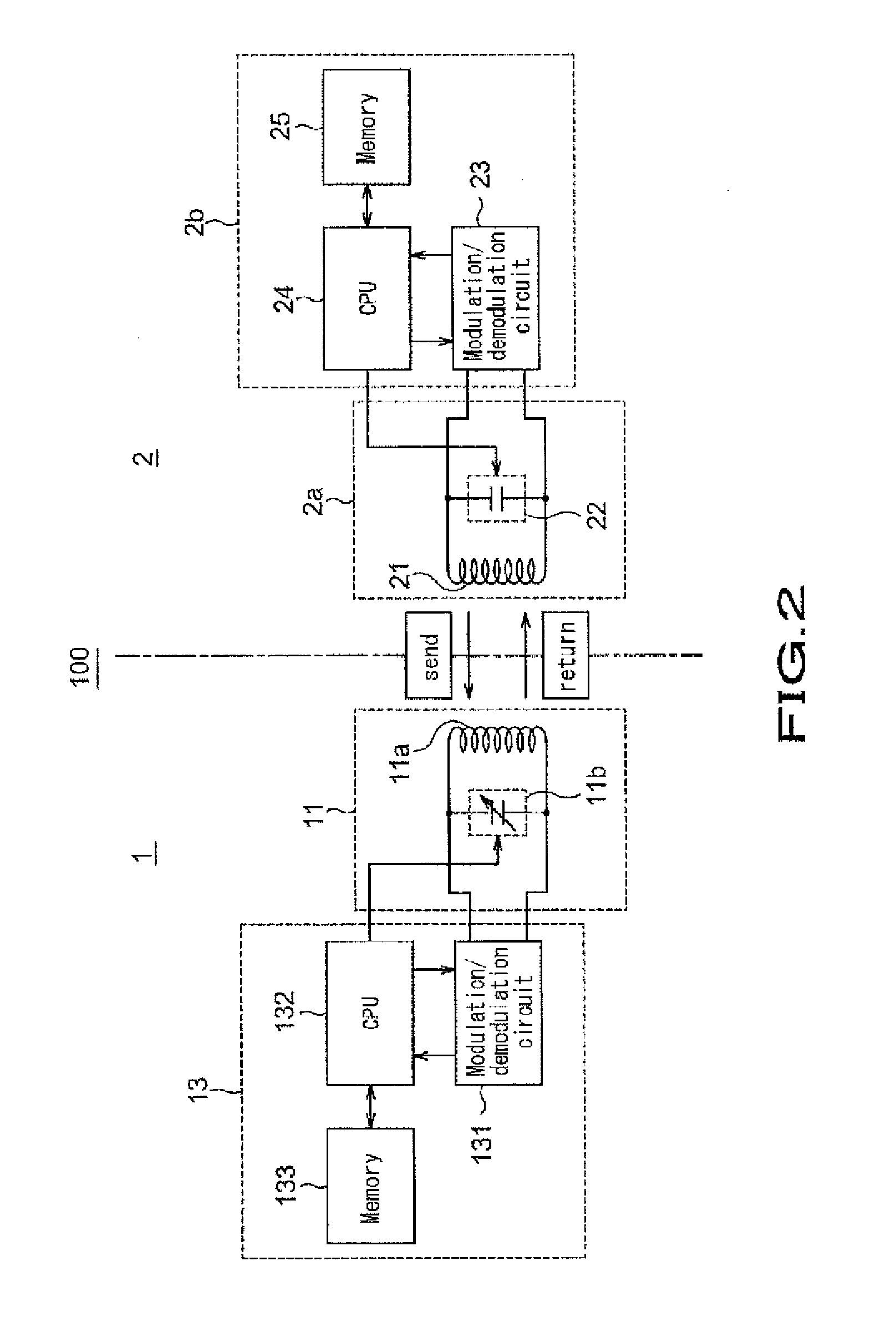
[0012]According to the present invention, a magnetic sheet is formed at a face-to-face position with respect to the antenna coil. This magnetic sheet has such temperature characteristic that causes the inductance of the antenna coil to be changed with a sign of change (characteristic) opposite to that of the capacitance of the capacitor brought about by changes in temperature in the working temperature range. Owing to such change in the inductance of the antenna coil, the resonance frequency of the resonance circuit may be brought into coincidence approximately with the oscillation frequency. According to the present invention, the changes in the resonance frequency caused by changes in the capacitance of the capacitor brought about by changes in temperature may be canceled out by changes in the inductance of the antenna coil in response to the temperature characteristic of the magnetic sheet. The resonance frequency may thus be maintained approximately constant, even though the temperature is changed in the preset working temperature range, thus providing for stabilized communication.

Problems solved by technology

However, the constant LC of the loop antenna and the capacitor for resonance has a number of factors of variations and may not necessarily be set at a scheduled value.

Method used


Image

  • Antenna device and communication device
  • Antenna device and communication device
  • Antenna device and communication device

Examples


example 1

[0082]In the following, with the use of circuit elements, as used in an actual antenna circuit, the communication characteristic of the antenna module of the above described embodiment will be explained in detail.

[0083]In the following Example, the resonance frequency of the antenna circuit in the vicinity of 20° C. is tuned to 13.56 [MHz], which is the frequency transmitted from the reader / writer 2, and evaluation was made of the deviations of the resonance frequency at 0° C. to 60° C. as the operating frequency range.

[0084]A multi layered ceramic capacitor with a temperature characteristic shown in FIG. 8 was used as a capacitor for resonance of the antenna circuit. As shown in FIG. 8, the layered ceramic capacitor is among so-called variable capacitors, and has deviations of ±5% in terms of a variation dc / c within a temperature range of −55° C. to 85° C.

[0085]It is noted that, as also shown in FIG. 8, the capacitance of the variable capacitor is varied in an ‘upwardly convex’ pat...


PUM


Abstract

An antenna device includes an antenna coil that receives a magnetic field transmitted from a reader / writer and a capacitor. The antenna device also includes a magnetic sheet formed at a face-to-face position with respect to the antenna coil and configured for changing the inductance of the antenna coil. The capacitor has a temperature characteristic in which the capacitance of the capacitor is changed with changes in temperature. The magnetic sheet is formed of a magnetic material having a temperature characteristic in which the inductance of the antenna coil is made to be changed with an opposite sign of change to that of the capacitance of the capacitor that is changed with changes in temperature in the working temperature range. In this manner, the resonance frequency of the antenna circuit in the working temperature range may be brought approximately into coincidence with the oscillation frequency of the reader / writer.

Description

[0001]The present application claims priority rights which are based on the Japanese patent application No. 2009-175751 filed in Japan on Jul. 28, 2009 and is a continuation-in-part of U.S. patent application Ser. No. 13 / 361,435, filed on Jan. 30, 2012, which is a continuation application of PCT / JP2010 / 062618, filed on Jul. 27, 2010, which claims priority to JP 2009-175751. The contents of the patent application of the senior filing data are to be incorporated by reference into the present patent application.FIELD OF THE INVENTION[0002]This invention relates to an antenna device that provides for a communication enabled state by electromagnetic induction between it and a transmitter that transmits a magnetic field, and to a communication device with the antenna device built in the communication device.BACKGROUND OF THE INVENTION[0003]In these days, the near field communication technology of signal transmission and reception by electromagnetic induction has been established and its u...

Claims


Application Information

Patent Timeline
Patent Type & Authority Applications(United States)
IPC IPC(8): H01Q1/00
CPCG06K19/0773G06K19/07749G06K19/07771H01Q9/27H01Q7/06H01Q7/08H01F27/008
Inventor ORIHARA, KATSUHISASUGITA, SATORUSAITO, NORIOKANNO, MASAYOSHI
Owner DEXERIALS CORP
Learn More