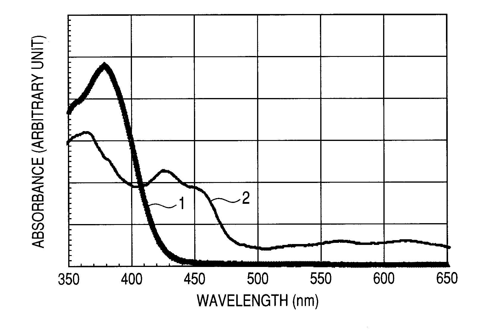
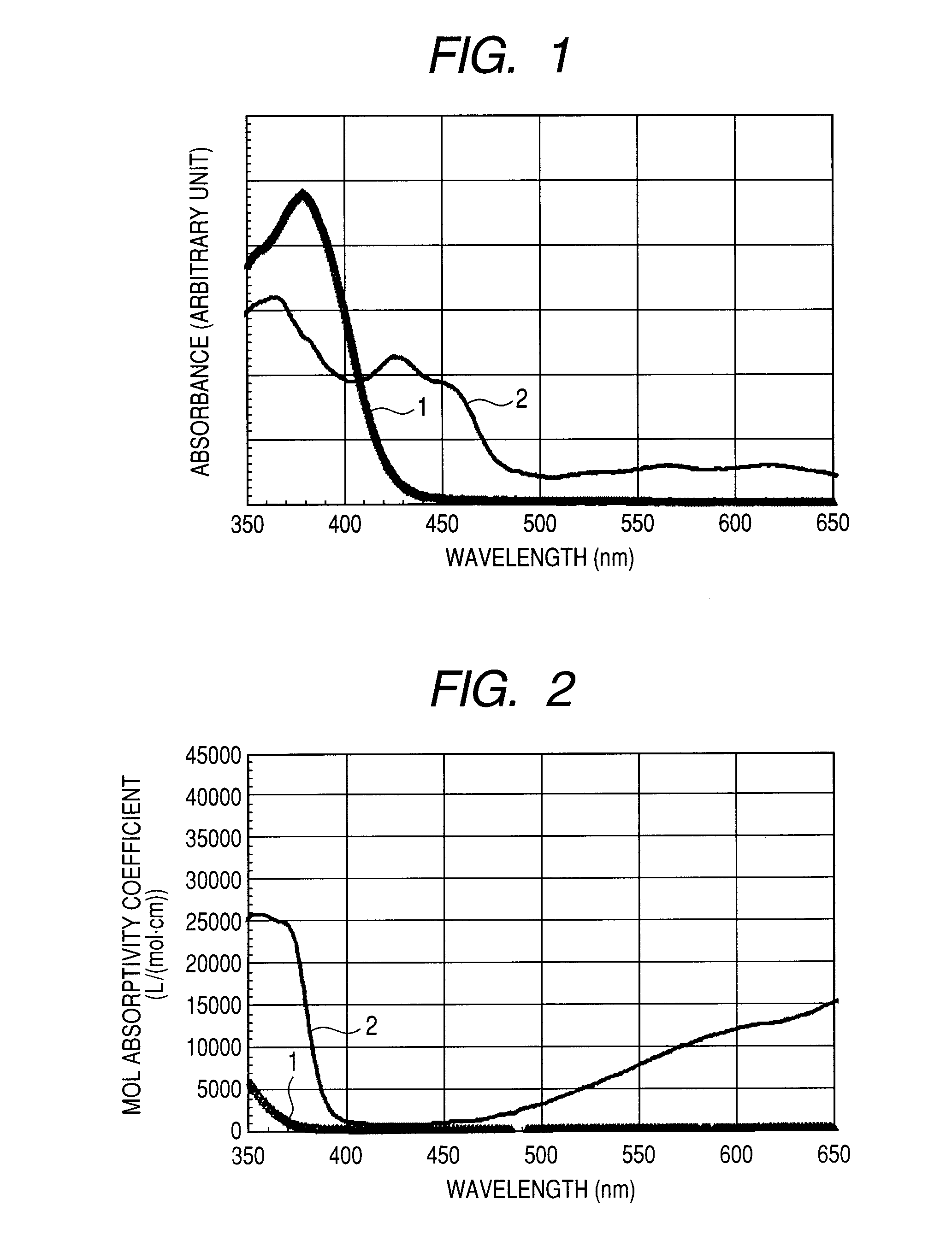
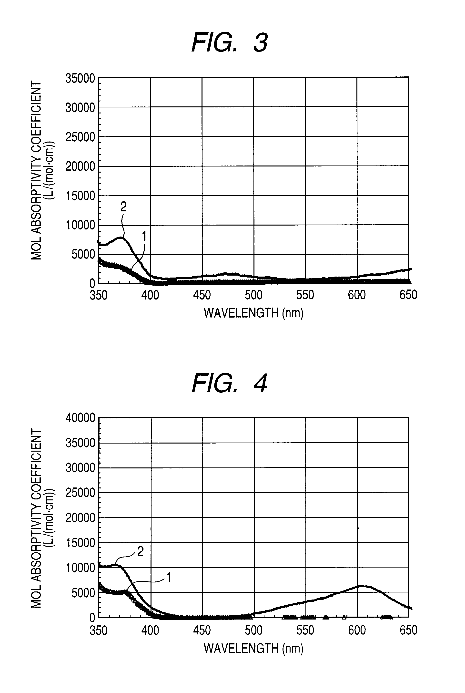
Organic light emitting device
a light-emitting device and organic technology, applied in thermoelectric devices, electrographic processes, instruments, etc., can solve the problems of degrading the constituent materials the decrease of the emission intensity of the organic light-emitting device with time, and achieve the effect of enhancing durability
- Summary
- Abstract
- Description
- Claims
- Application Information
AI Technical Summary
Benefits of technology
Problems solved by technology
Method used
Image
Examples
synthesis example 1
Synthesis of Exemplary compound 1
[0066]Exemplary compound 1 was synthesized by the following synthesis scheme.
(1) Synthesis of Intermediate Compound 1
[0067]The following reagents and solvents were charged into a 300-ml three-necked flask.
Compound x1: 10 g (36.2 mmol)
Compound x2: 14.98 g (47.1 mmol)
Toluene: 120 ml
Ethanol: 20 ml
[0068]Next, after the atmosphere in the reaction system was replaced with nitrogen, an aqueous solution of a mixture of 10 g of sodium carbonate and 100 ml of water was dropped to the reaction solution with stirring at room temperature, and then, 2.00 g (1.70 mmol) of tetrakis(triphenylphosphine)palladium(0) were added to the solution. Then, the reaction solution was heated to 77° C. and stirred at this temperature (77° C.) for 5 hours. After the completion of the reaction, an organic layer was extracted with toluene and dried over anhydrous sodium sulfate, and thereafter, the solvent was distilled off under reduced pressure to afford a crude product. Next, the...
synthesis example 2
Synthesis of Exemplary compound 2
[0078]Exemplary compound 2 was synthesized by the following synthesis scheme.
[0079]The following reagents and solvent were charged into a 300-ml three-necked flask.
3′-Iodo-1,1′:5′,1″-terphenyl: 4 g (purity: 93%, 10.5 mmol)
Lithium amide (trade name, manufactured by Kishida Chemical Co., Ltd.): 2.68 g (111 mmol)
Sodium tert-butoxide (trade name, manufactured by Tokyo Chemical Industry Co., Ltd.): 3.41 g (34.8 mmol)
Xylene: 150 ml
[0080]Next, after the atmosphere in the reaction system was replaced with nitrogen, 3.7 ml (0.15 mmol) of tri-tert-butylphosphine (10% by weight hexane solution) were added to the reaction solution with stirring at room temperature. Then, 0.37 mg (0.65 mmol) of palladium dibenzylideneacetone (trade name, manufactured by Tokyo Chemical Industry Co., Ltd.) was added. Then, argon was introduced into the flask to replace the reaction system with argon. After that, the reaction solution was stirred for 6 hours with heating and reflux....
synthesis example 3
Synthesis of Exemplary compound 3
[0084]Exemplary compound 3 was synthesized by the following synthesis scheme.
[0085]The following reagents and solvent were charged into a 100-ml three-necked flask.
3-Bromofluorene: 0.40 g (1.46 mmol)
Lithium amide (trade name, manufactured by Kishida Chemical Co., Ltd.): 0.35 g (14.6 mmol)
Sodium tert-butoxide (trade name, manufactured by Tokyo Chemical Industry Co., Ltd.): 0.49 g (5.0 mmol)
Xylene: 20 ml
[0086]Next, 0.5 ml (0.15 mmol) of tri-tert-butylphosphine (10% by weight hexane solution) was added to the reaction solution with stirring at room temperature under a nitrogen atmosphere. Then, 0.67 mg (0.153 mmol) of palladium dibenzylideneacetone (trade name, manufactured by Tokyo Chemical Industry Co., Ltd.) was added. Then, argon was introduced into the flask to replace the reaction system with argon. After that, the reaction solution was stirred for 6 hours with heating and reflux. After the completion of the reaction, an organic layer in the react...
PUM
 Abstract
Description
Claims
Application Information
 - R&D
- Intellectual Property
- Life Sciences
- Materials
- Tech Scout
- Unparalleled Data Quality
- Higher Quality Content
- 60% Fewer Hallucinations
Browse by: Latest US Patents, China's latest patents, Technical Efficacy Thesaurus, Application Domain, Technology Topic, Popular Technical Reports.
© 2025 PatSnap. All rights reserved.Legal|Privacy policy|Modern Slavery Act Transparency Statement|Sitemap|About US| Contact US: help@patsnap.com


