
Mobile solar-powered light tower

a solar energy and light tower technology, applied in the field of mobile solar energy light towers, can solve the problems of environmental damage, limited known devices, and potential adverse health effects on individuals working or otherwise located, and achieve the effects of eliminating noise pollution, and eliminating the dependency on fossil fuels

Active Publication Date: 2012-08-09
RENEWABLE ENERGY HLDG
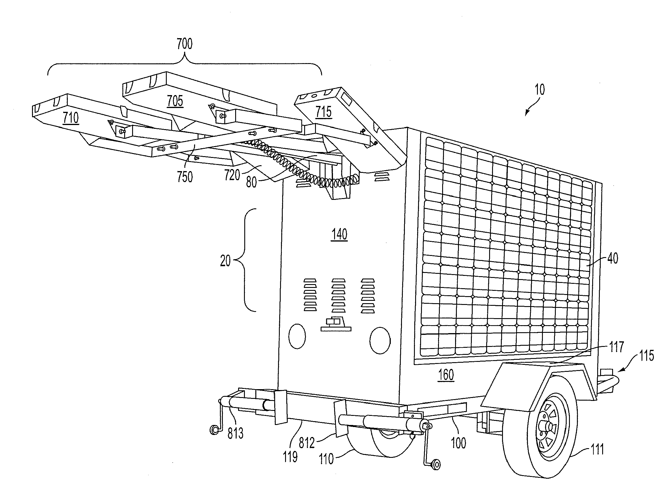
View PDF7 Cites 62 Cited by
  • Summary
  • Abstract
  • Description
  • Claims
  • Application Information

AI Technical Summary

Benefits of technology

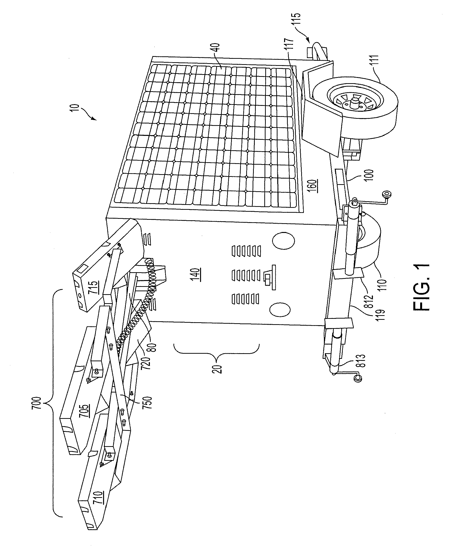
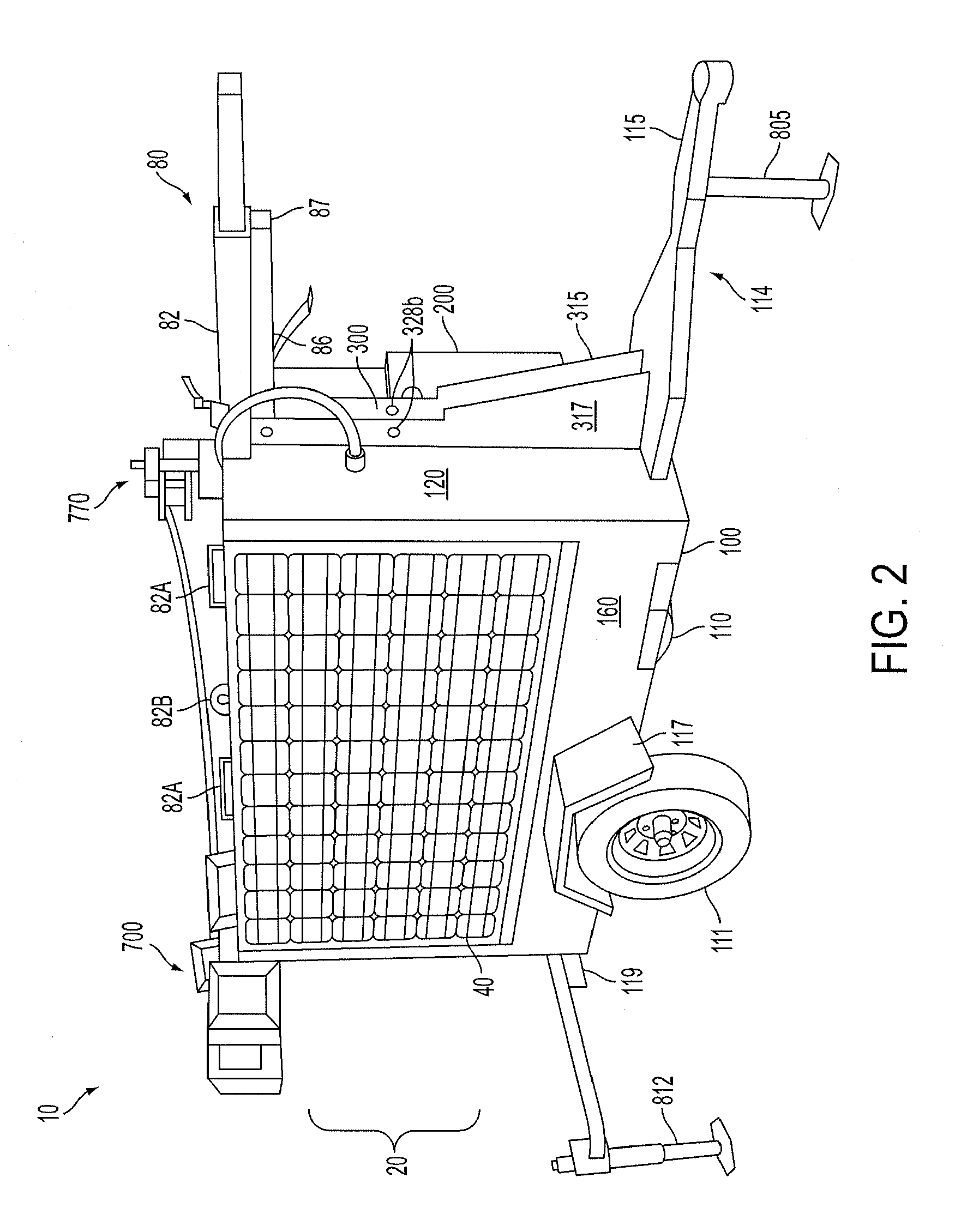
[0004]The present invention meets many needs in the art by providing functional, cost-effective, mobile lighting that can be powered by clean, renewable, solar energy that eliminates the dependency on fossil fuel in relation to providing such lighting and that also eliminates associated carbon emissions, as well as any noise pollution. In particular embodiments, the present invention relates to a mobile lighting system and device that provides excellent and useful lighting on-demand and at any site where the relatively compact device may be positioned. The system and device utilizes a renewable energy source, particularly solar energy, to charge and recharge an on-board battery or suite of batteries that provide power to a light emitting device (e.g., comprising light emitting diodes or “LED” floodlights) that is positioned atop a mast that can be adjusted to varying heights and orientations to most effectively light a defined area for a variety of uses, such as recreation events, camping, sports events, construction and other work activities, mining, security, emergency situations, airport uses, military operations, storm or disaster recovery, and the like.
[0005]In various embodiments, the invention can relate to a mobile solar lighting device that can include an extendable mast that is connected at one end portion to a base unit, and that is connected at an opposing end portion to a lighting module, such as a high output LED floodlight. The base unit may be constructed upon a device for facilitating mobility of the device, such as a trailer. The solar lighting device also can include one or more solar power modules (e.g., solar panels) that can be moved between modes that optimize mobility of the solar lighting device and modes that optimize receipt of solar energy and thus optimize charging. The inventive device further can include a battery or batteries (i.e., a battery “bank” or battery “suite”) that can be housed in a housing unit that specifically can be attached to or formed on a trailer frame or floor / deck. The mast beneficially can be raised, lowered, and rotated to a variety of positions. In operation, the solar panels (or other renewable energy acquisition device) can be used to form electrical current that is used to charge the batteries. The charged batteries are useful to provide electrical power to a load such as the lighting module and thus provide a light source that, in various embodiments, is mobile, self-contained, renewable energy powered, emission-free, and noiseless.
[0006]In specific embodiments, a mobile, solar power lighting device according to the present invention may comprise the following: a base housing unit having two opposing side walls; one or more solar power modules pivotally attached to one or both of the opposing side walls of the base housing unit, the solar power modules being effective to convert solar energy into electrical current; one or more batteries positioned within the base housing unit, the one or more batteries being at least partially rechargeable using the electrical current formed by the solar power modules; a lighting module that is at least partially powered using the one or more batteries; and a mast having a first end section for connection to the base housing unit and having a second, opposing end section for connection to the lighting module, the mast being one or more of extendable, pivotable, and rotatable. In some embodiments, the base housing unit more particularly may include the following: a trailer frame; a front wall and a back wall interconnecting the two opposing side walls, wherein the front wall, back wall, and side walls are attached to the trailer frame; and a roof attached to the front wall, the back wall, and the opposing side walls. In specific embodiments, the roof of the base housing unit can include a recessed portion that extends along an approximate midline from front to back, and such recess can be useful for receiving the mast when pivoted in a down position. This beneficially assists in protecting the mast during transport and can reduce the profile of the device when in a transport configuration.

Problems solved by technology

Although effective for providing mobile lighting, such known devices have limitations because of the operating expense and labor of constantly providing maintenance and fuel to power the generator, the significant noise associated with such generators, and the undesirable emissions related to fossil fuel combustion that not only can be environmentally detrimental but also can have potential adverse health effects on individuals working or otherwise located in the general vicinity of the fossil fuel-powered devices.

Method used


Image

  • Mobile solar-powered light tower
  • Mobile solar-powered light tower
  • Mobile solar-powered light tower

Examples


Embodiment Construction

[0029]The invention now will be described more fully hereinafter through reference to various embodiments. These embodiments are provided so that this disclosure will be thorough and complete, and will fully convey the scope of the invention to those skilled in the art. Indeed, the invention may be embodied in many different forms and should not be construed as limited to the embodiments set forth herein; rather, these embodiments are provided so that this disclosure will satisfy applicable legal requirements. As used in the specification, and in the appended claims, the singular forms “a”, “an”, “the”, include plural referents unless the context clearly dictates otherwise.

[0030]In certain aspects, the present invention provides mobile, solar-powered lighting devices. The devices are compact, durable, and useful to provide excellent, high efficiency lighting at various sites without associated emissions, noise, or need for fossil fuels.

[0031]In certain embodiments, a mobile, solar-p...


PUM


Abstract

Provided is a mobile lighting device that can derive power from a renewable energy source, such as solar power. The device can comprise a mobile base unit that can house one or more components of the device. The device further can comprise a solar power module associated with the mobile base unit that converts solar energy into electrical current. The device also can comprise a lighting module associated with the mobile base unit that is at least partially powered either directly or indirectly using the electrical current from the solar power module. The device further can comprise a solar power storage module, such as comprising one or more batteries, for storing energy and discharging as electrical current for powering the lighting module, which can be positioned atop a mast that can be extendable, pivotable, and / or rotatable. The invention also provides methods and systems for illuminating areas.

Description

FIELD OF THE INVENTION[0001]The present invention relates to mobile lighting systems. More particularly, the invention relates to mobile lighting systems that make high efficiency use of solar energy for providing lighting at various locations.BACKGROUND[0002]Many outdoor activities that are performed during daytime hours may be performed during nighttime hours if an adequate light source is available. To accommodate outdoor activities during nighttime hours (such as large sporting events), floodlights or similar lighting devices are used. Such outdoor lighting, however, is typically permanently positioned and directly connected to an electric power grid.[0003]Many nighttime activities benefit from the ability to provide lighting that is mobile. For example, much construction is carried out during nighttime hours to minimize any negative impact of the construction on local activities during daytime hours, which are typically busier. To provide mobile lighting, the field typically ha...

Claims


Application Information

Patent Timeline
Patent Type & Authority Applications(United States)
IPC IPC(8): F21L4/08
CPCF21L4/08F21S9/032B60Q1/24F21W2131/10F21K9/30F21V21/22F21V21/26B62D63/08F21K9/20
Inventor ROBERTSON, DANIEL LEEORFF, JR., RICHARD WARRENWINGO, JR., EARL RANDOLPH
Owner RENEWABLE ENERGY HLDG
Learn More