Microscope with a sheet of light

a microscope and light technology, applied in the field of microscopes, can solve the problems of limiting the use of spim technology in the commercial, affecting the quality of the image field,

Active Publication Date: 2012-08-09
CARL ZEISS MICROSCOPY GMBH
View PDF7 Cites 41 Cited by
  • Summary
  • Abstract
  • Description
  • Claims
  • Application Information

AI Technical Summary

Benefits of technology

[0023]An advantage of embodiments of the invention is that the size of the detection image field can be continuously varied by means of the optical detection element; secondly, the detection element can be used to continuously displace a detection focal plane in the sample region. The detection element may be designed in such a way that it performs only one of these two tasks, or can be used to perform both settings either alternately or simultaneously. The detection element may be an integral part of the detection objective, say, in the form of two or more lens components movable relative to each other, with the front lens remaining stationary during the movement of these lens components. Alternatively, the detection element may be a separate component in the beam path, arranged at some distance from the detection objective.
[0051]Instead of arranging the beam splitter in the near-infinity space of the beam path, the dichroic beam splitter may also be arranged in the divergent part of the beam path between the array detectors and an optical imaging element for imaging the light to be detected onto the array detectors. In the branch beam path that captures the light transmitted by the beam splitter, then, a glass plate of identical thickness as the beam splitter may be arranged between array detector and beam splitter, the glass plate and the beam splitter enclosing an angle of approximately 90°. In this way, any astigmatism caused by the use of the beam splitter in the transmission branch beam path is corrected.

Problems solved by technology

All the setups and methods known in prior art, however, have more or less grave disadvantages, which restrict the use of the SPIM technology in the commercial sphere, where it is important, among other things, to achieve a high user friendliness of the microscopes and, as a rule, a high throughput, with a great number of samples having to be examined within a relatively short time.
In most of the setups using SPIM technology that have been implemented so far, e.g., those according to DE 102 57 423 A1 and WO2004 / 053558A1, the mere variation of the image field size for detection—e.g., switching from an image field size providing a good overview of the sample to a detail region—is rather a complex and time-consuming affair.
This affects the sample space unfavorably, which may have a particularly negative effect in case of a horizontal detection beam path.
Moreover, the sample is unnecessarily heated or cooled.
Nevertheless, slight interactions with the sample chamber and, thus, indirectly with the sample cannot be avoided.
This, too, is inserted into the sample chamber from above, which is, as a rule, filled with an immersion liquid, so that, here again, there are slight interactions with the sample chamber when the zoom function of the objective is working or when the focus is adjusted, alone because of the motorized shifting of the lenses, which may cause vibrations that may transmit to the liquid in the sample chamber.
The flare occurring in case of diaphragms causes light losses, whereas the use of beam expanders reduces flexibility, since exchanging them is rather laborious.
If plain scanning is combined with angular scanning, i.e. illumination from different angles, in order to reduce banding as described, e.g., in DE 10 2007 015 063 A1, there is a risk that beat artefacts will be produced if the scanners for light sheet angle scanning and position scanning are not matched, i.e. not synchronized.
For many kinds of samples, such as embryos of the fruit fly (Drosophila), such a setup is not of advantage, because in this way scattering and non-scattering image portions are combined in an unfavorable way.
This applies especially to horizontal detection beam paths with immersed detection objectives: Here, the necessary movement of the objective entails tightness problems.
On the other hand, a movable element in the sample space is disturbing in general, as the user may need space there for diverse means for feeding to the sample chamber.
The vibrations occurring during the movement of the objective may be unfavorably transmitted to the sample, since the space between the objective and the sample is occupied by a liquid rather than by air.
If scanners are used for producing the light sheet, the imaging of the scanner into the pupil of the illumination objective is not optimal, as a rule, so that the plain position scanning is superposed by portions of angular scanning.
In the direction of the reflected light, however, image artefacts such as astigmatism or also defocusing do occur, due to surface tensions at the dichroic filter, which can be caused, e.g., by the coating, or by improper installation.
As far as the reflected branch beam path is concerned, though, the problem of surface tensions may occur here, too, if conventional dichroic filters are used.

Method used


Image

  • Microscope with a sheet of light
  • Microscope with a sheet of light
  • Microscope with a sheet of light

Examples


Embodiment Construction

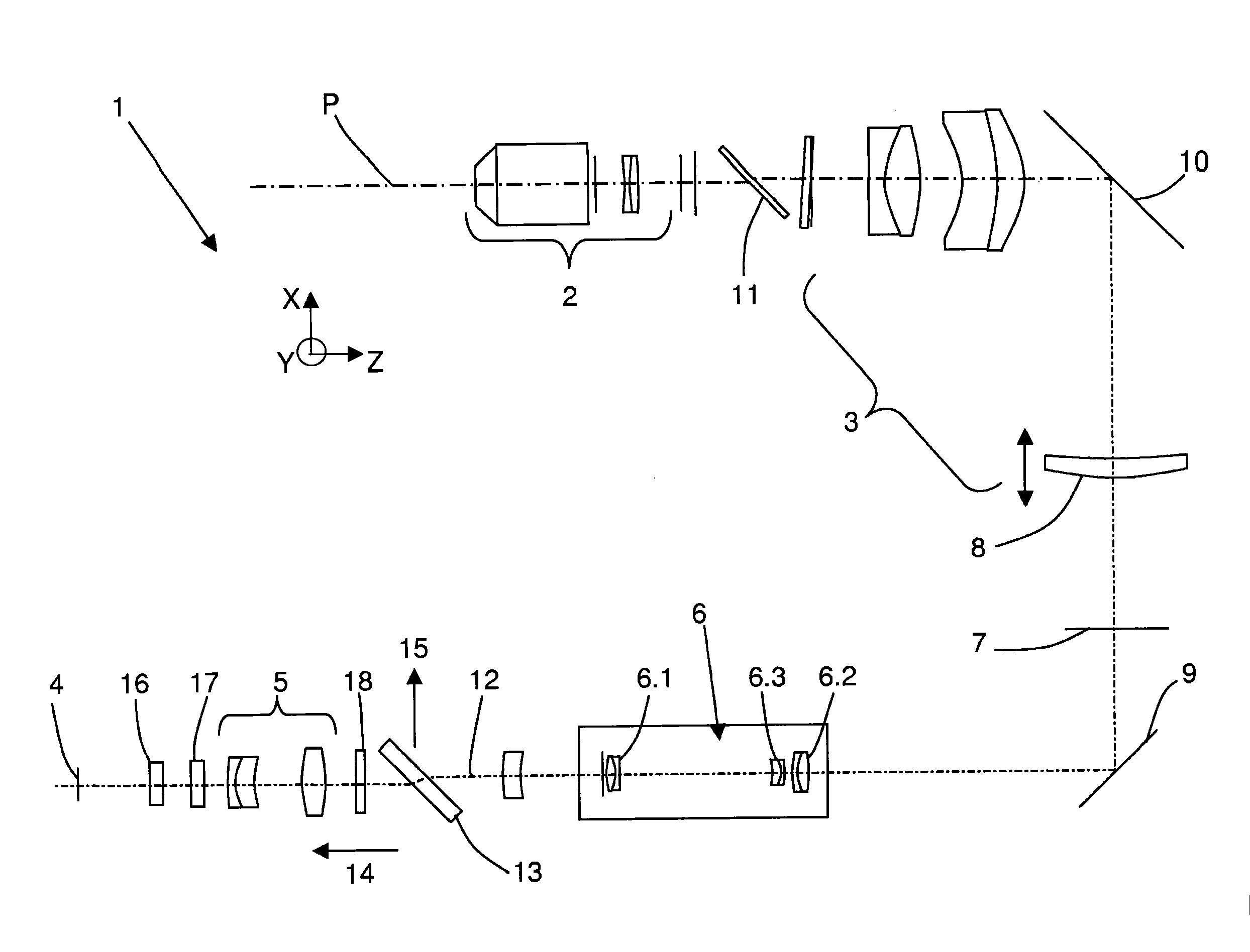
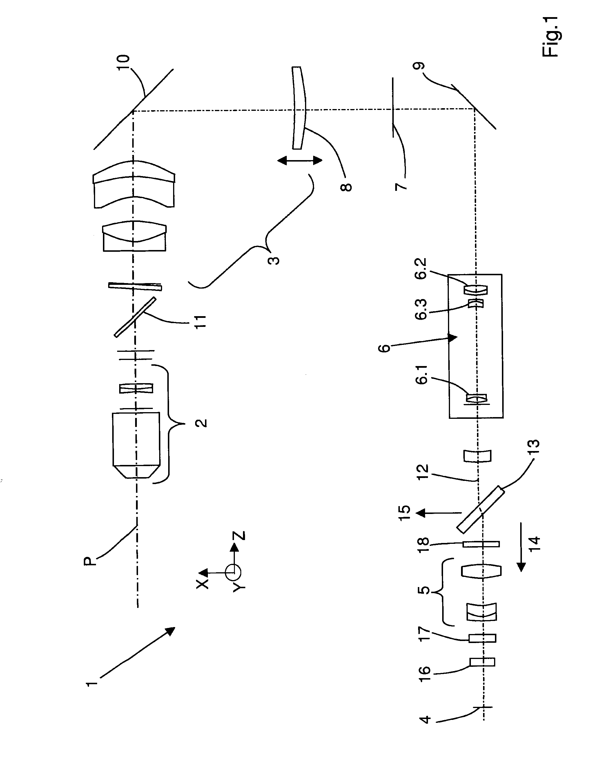
[0063]FIG. 1 shows a detection beam path of a microscope operating by the principle of SPIM technology. Pertaining to it, though not shown in FIG. 1, is an illumination device of the microscope, with which a light sheet for illuminating a sample region P is generated. In the direction of an illumination axis X of an illumination beam path and in the direction of a transverse axis Y lying across the illumination axis X, the light sheet has an approximately planar form. Shown along the detection beam path are elements of a detection device 1 used to detect light that is radiated by the sample region P along a detection axis Z. The illumination axis X and the detection axis Z are approximately perpendicular to each other, as are the transverse axis Y and the detection axis Z.

[0064]The detection device 1 comprises a detection objective 2 arranged in the detection beam path. Other essential elements in the detection beam path 1 are a tube lens unit 3 and a spatially resolving array detec...


PUM


Abstract

A family of microscopes with illumination systems directing a sheet of light having an approximately planar extension in an illumination axis of an illumination beam path and in a transverse axis orthogonally oriented to the illumination axis. The microscopes have detection devices used to detect light that is emitted by a sample region. The detection devices including a detection lens system disposed in the detection beam path and an optical detection element spaced from a front lens of the detection lens system and independently adjustable thereof. The optical detection element continuously varies the size of a detection image field and / or continuously displaces a focal plane of detection in the P-region.

Description

PRIORITY CLAIM[0001]The present application is a National Phase entry of PCT Application No. PCT / EP2010 / 063665, filed Sep. 17, 2010, which claims priority from German Application Number 102009044983.3, filed Sep. 24, 2009, the disclosures of which are hereby incorporated by reference herein in their entirety.FIELD OF THE INVENTION[0002]The invention relates to a microscope comprising an illumination device which produces a light sheet to illuminate a sample region, the said sheet having an approximately planar extension in the direction of an illumination axis X of an illumination beam path and in the direction of a transverse axis Y lying across the illumination axis X. The microscope further comprises a detection device used to detect light that is radiated by the sample region along a detection axis Z of a detection beam path, the illumination axis X and the detection axis Z as well as the transverse axis Y and the detection axis Z being oriented relative to each other at an angl...

Claims


Application Information

Patent Timeline
IPC IPC(8): H04N7/18
CPCG02B21/002G02B21/241G02B21/06
Inventor LIPPERT, HELMUTPOWER, CHRISTOPHERHAUSCHILD, ROBERTWALD, MATTHIAS
Owner CARL ZEISS MICROSCOPY GMBH
Why Eureka
Try Eureka