
Intervertebral implant

a technology of intervertebral implants and implants, which is applied in the field of medical devices for the spine, can solve the problems of high cost, long in-patient hospital stays, and increased pain associated with open procedures, and achieves the effects of reducing the risk of fracture, and improving the quality of li

Inactive Publication Date: 2012-08-02
INTERVENTIONAL SPINE
View PDF4 Cites 104 Cited by
  • Summary
  • Abstract
  • Description
  • Claims
  • Application Information

AI Technical Summary

Benefits of technology

[0012]While using minimally invasive procedures to deploy an intervertebral prostheses is generally advantageous, such procedures do have the disadvantages of generally requiring t

Problems solved by technology

Additionally, the vertebrae and associated connective elements are subject to injuries, including fractures and torn ligaments and surgical manipulations, including laminectomies.
Notwithstanding the variety of efforts in the prior art described above, these intervertebral implants and techniques are associated with another disadvantage.
In particular, these techniques typically involve an open surgical procedure, which results in higher cost, lengthy in-patient hospital stays and the pain associated with open procedures.
This results in additional movement of the patient.
While using minimally invasive procedures to deploy an intervertebral prostheses is generally advantageous, such procedures do have the disadvantages of generally requiring the device to be passed through a relatively small diameter passage or tube.
As described, an intervertebral implant is typically limited in size by the size of the passage or tube through which the implant must fit to reach the intervertebral space.
However, these implants required complicated and / or large deployment tools.

Method used


Image

  • Intervertebral implant
  • Intervertebral implant
  • Intervertebral implant

Examples


Embodiment Construction

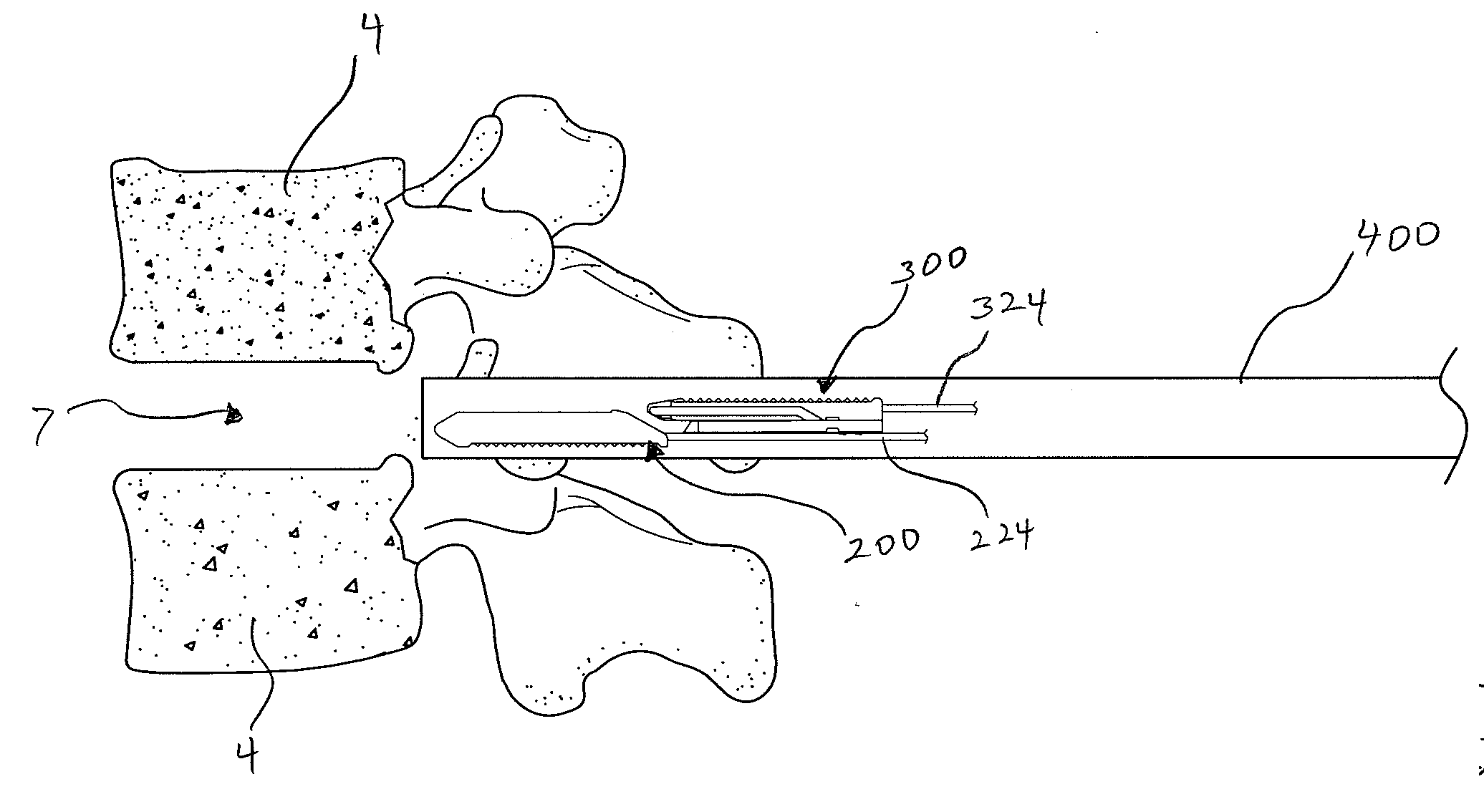
[0042]In accordance with some embodiments disclosed herein, an intervertebral implant is provided that allows the clinician to insert the intervertebral implant through a minimally invasive procedure. For example, in one embodiment, one or more intervertebral implants can be inserted percutaneously to reduce trauma to the patient and thereby enhance recovery and improve overall results of the surgery. By minimally invasive, Applicant means a procedure performed percutaneously through an access device in contrast to a typically more invasive open surgical procedure. Such access devices typically provide an elongated passage that extends percutaneously through the patient to the target site. Examples of such access devices include, but are not limited to, endoscopes and the devices described in U.S. Patent Application Publication Nos. 2006-0030872 and 2005-0256525 and U.S. Pat. Nos. 6,793,656, 7,223,278 and co-pending U.S. Patent Application No. 13 / 245,130 filed Sep. 26, 2011 (Attorne...


PUM

PropertyMeasurementUnit
Heightaaaaaaaaaa
Shapeaaaaaaaaaa
Dimensionaaaaaaaaaa

Abstract

An intervertebral implant and related methods of use are provided for treatment of spaces between two vertebrae. The implant can comprise a first member and a second member that are configured for engagement in a stacked configuration. The first member and second member can be inserted separately so that the intervertebral space can be reached through limited access pathways. The first member and second member can be coupled in situ in the intervertebral space to form an implant of desired height. In this manner, an intervertebral implant having final dimensions that would not fit through a limited access pathway can be implanted through the access pathway by inserting the implant in separate member pieces.

Description

PRIORITY[0001]The present application claims the benefit of U.S. Provisional Application No. 61 / 438,046, filed Jan. 31, 2011, the disclosure of which is hereby incorporated by reference herein in its entirety.BACKGROUND[0002]1. Field of the Disclosure[0003]The present application relate to medical devices and, more particularly, to a medical device for the spine.[0004]2. Description of the Related Art[0005]The human spine is a flexible weight bearing column formed from a plurality of bones called vertebrae. There are thirty-three vertebrae, which can be grouped into one of five regions (cervical, thoracic, lumbar, sacral, and coccygeal). Moving down the spine, there are generally seven cervical vertebrae, twelve thoracic vertebrae, five lumbar vertebrae, five sacral vertebrae, and four coccygeal vertebrae. The vertebrae of the cervical, thoracic, and lumbar regions of the spine are typically separate throughout the life of an individual. In contrast, the vertebra of the sacral and c...

Claims


Application Information

Patent Timeline
IPC IPC(8): A61F2/44
CPCA61F2/30724A61F2310/00592A61F2/442A61F2/447A61F2/4611A61F2002/2817A61F2002/2835A61F2002/30013A61F2002/30014A61F2002/30062A61F2002/30079A61F2002/30387A61F2002/304A61F2002/30401A61F2002/30433A61F2002/30448A61F2002/30461A61F2002/30484A61F2002/30556A61F2002/30563A61F2002/30579A61F2002/30599A61F2002/30607A61F2002/30616A61F2002/30841A61F2310/00023A61F2310/00293A61F2310/00359A61F2310/00407A61F2/30734A61F2002/30011
Inventor CUEVAS, WALTERFLOWER, ROBERTOLMOS, FAUSTOWARREN, CHRISTOPHERDAVIS, PETER
Owner INTERVENTIONAL SPINE
Learn More