Electronic cassette charger
a charger and cassette technology, applied in the field of electronic cassette chargers, can solve problems such as contact failure, and achieve the effect of less dirt adhesion
- Summary
- Abstract
- Description
- Claims
- Application Information
AI Technical Summary
Benefits of technology
Problems solved by technology
Method used
Image
Examples
first embodiment
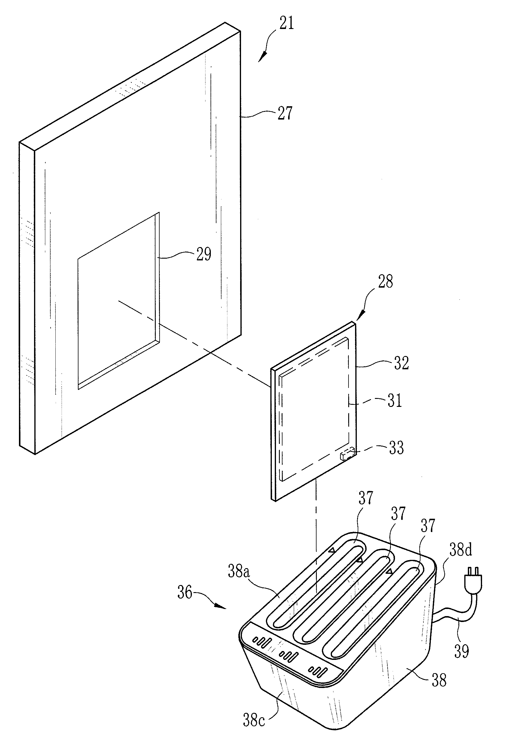
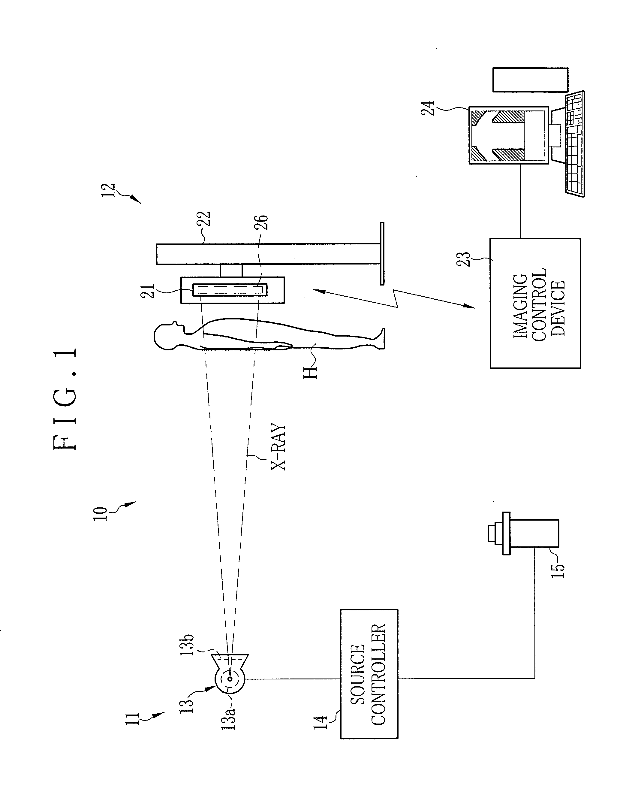
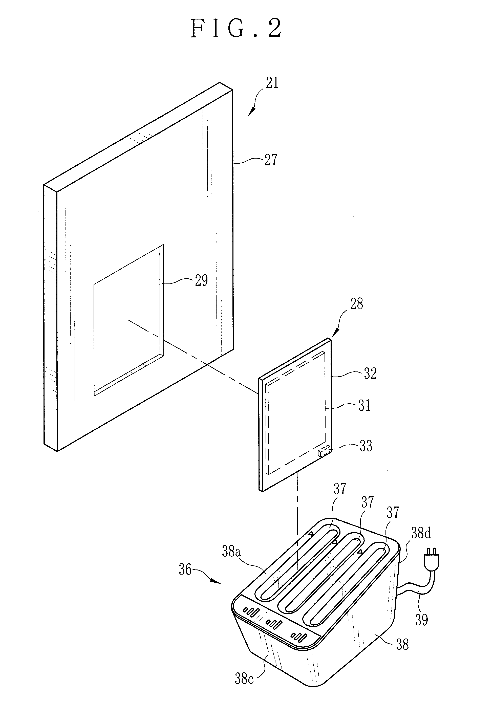
[0021]In FIG. 1, an X-ray imaging system 10 includes an X-ray generation device 11 and an X-ray imaging apparatus 12. The X-ray generation device 11 is constituted of an X-ray source 13, a source controller 14 for controlling the X-ray source 13, and an irradiation switch 15. The X-ray source 13 has an X-ray tube 13a for irradiating X-rays and an irradiation field limiter (collimator) 13b for limiting irradiation field of X-rays irradiated from the X-ray tube 13a.
[0022]The X-ray tube 13a has a cathode made of filament which emits thermal electrons and an anode (target) which irradiates X-rays after collision of the thermal electrons emitted from the cathode. The irradiation field limiter 13b is made of, for example, plural lead plates for shielding X-rays except for a middle portion. An irradiation opening for transmitting X-rays is formed in the middle portion of the irradiation field limiter 13b, in which the size of the irradiation opening is changed by moving the position of th...
second embodiment
[0064]In the above first embodiment, the insertion opening 41 is inclined in a same direction as the bottom surface 46, and the inclined angle of the insertion opening 41 is almost same as the inclined angle α of the bottom surface 46. However, as shown in a charger 61 of the second embodiment of FIG. 6, an inclined angle β (inclined angle to phantom line LH which extends in a horizontal direction) of the insertion opening 41 formed on an upper surface 62a of a main body 62 may be larger than inclined angle α of the bottom surface 46, i.e. α41 and the upper end side of the bottom surface 46 where the connecter 51 locates is deeper than that between the insertion opening 41 and the lower end side of the bottom surface 46, so that the risk for hitting the connecter 51 and the corner 28a can be reduced.
[0065]As described above, upon insertion of the battery pack 28 into the insertion opening 41, the operator guesses loading posture of the battery pack 28 from appearance of the main bod...
third embodiment
[0068]In a third embodiment shown in FIG. 7, an electronic cassette 73 incorporating a battery 72 is entirely loaded in a loading chamber 74. In the electronic cassette 73, a connecter 76 is provided near one corner of the casing. When the electronic cassette 73 is loaded in the loading chamber 74, the connecter 76 and a connecter at the charger side in the loading chamber 74 is electrically connected. The charger 71 is different from the charger 36 and the charger 61 in size only, and the parts having the same structure and function as the above first embodiment have the same reference numerals, and their description will not be repeated.
[0069]In the above embodiments, the example that the insertion opening 41 and the bottom surface 46 are inclined in a same direction, but the insertion opening 41 may extend in a horizontal direction without inclination or may be inclined in a direction opposite to the bottom surface 46. The result for preventing contact failure of the insertion op...
PUM
 Abstract
Description
Claims
Application Information
 - R&D
- Intellectual Property
- Life Sciences
- Materials
- Tech Scout
- Unparalleled Data Quality
- Higher Quality Content
- 60% Fewer Hallucinations
Browse by: Latest US Patents, China's latest patents, Technical Efficacy Thesaurus, Application Domain, Technology Topic, Popular Technical Reports.
© 2025 PatSnap. All rights reserved.Legal|Privacy policy|Modern Slavery Act Transparency Statement|Sitemap|About US| Contact US: help@patsnap.com


