
System for defining energy field characteristics to illuminate nano-particles used to treat invasive agents

a technology of energy field characteristics and nanoparticles, applied in electrotherapy, surgery, therapy, etc., can solve the problems of no procedure that can be used to accurately detect the presence of cancer cells in living organisms, reach a level of maturity, damage to living organisms, etc., and achieve high degree of accuracy

Active Publication Date: 2012-07-26
ENDOMAGNETICS LTD
View PDF1 Cites 5 Cited by
  • Summary
  • Abstract
  • Description
  • Claims
  • Application Information

AI Technical Summary

Benefits of technology

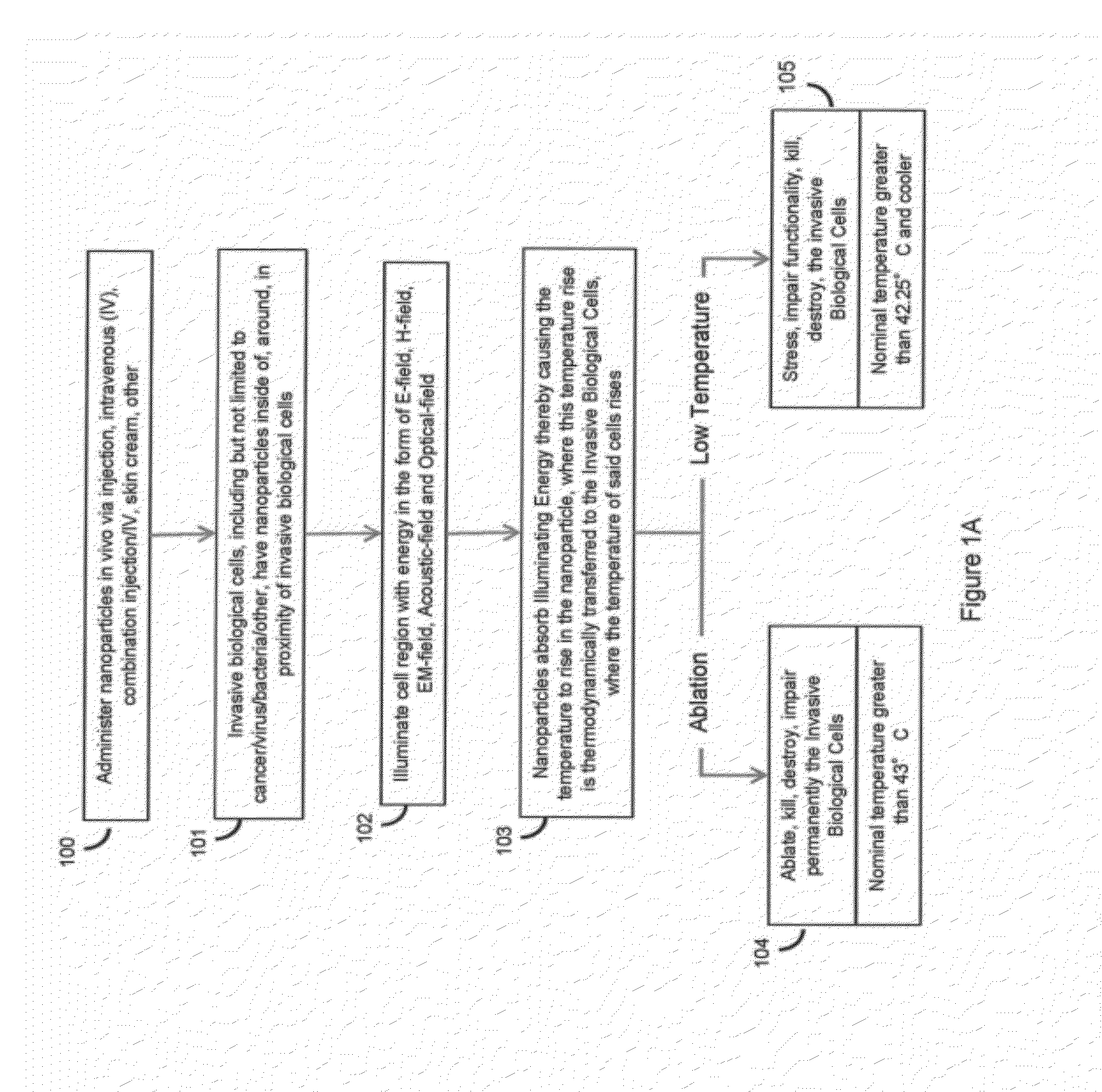
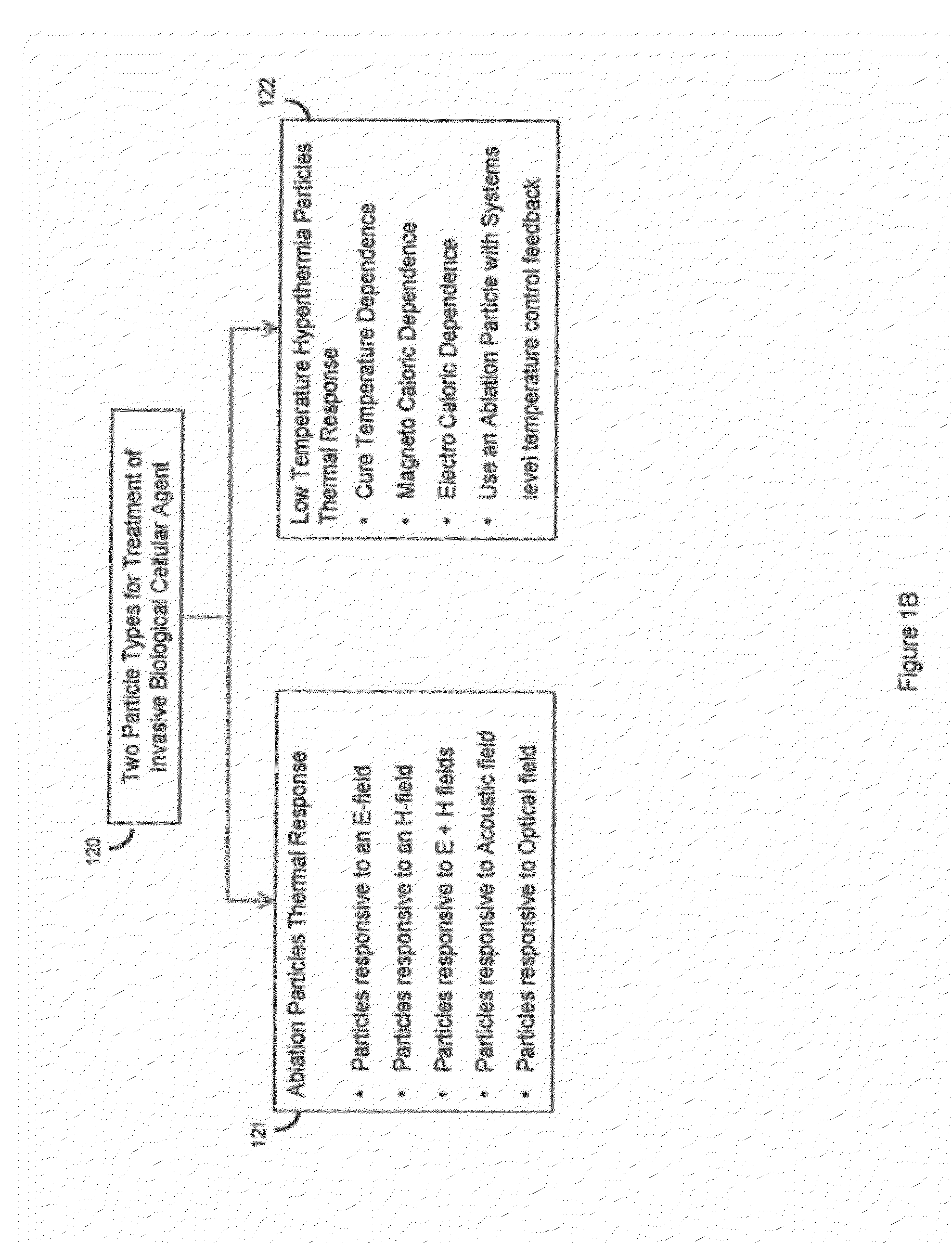
[0009]Two modes of cancer treatment are embodied herein: ablation and low temperature hyperthermia. In the ablation method, the nano-particles are illuminated by an energy field and the nano-particles thereby are heated to a temperature (for example greater than 42° C.) which causes the cells of the invasive agent to be heated to a temperature which kills the cancer cells over a given timeframe. The second method of cancer treatment uses Low Temperature Hyperthermia (LTH) to bring the nano-particles and the associated cancer cells to a temperature of 42.25° C. or cooler. This temperature causes the cancer cells, particularly cancer stem cells, to be stressed by a number of mechanisms which include: re-oxygenation, increased blood flow, change of acidity, and so on—environments that are harmful to cancer stem cells. By the application of the energy field to the nano-particles for a sufficient period of time, the heated cancer cells are destroyed with minimal production of Heat Shock Proteins, which enable cancer stem cells to survive normal killing temperatures.
[0012]Note that the locus of the cancer cells may be dynamic, such as in the case of a blood-borne cancer. In this example, the movement of the cancer cells within the blood stream creates an added complexity to the treatment process. In cancers that are in the process of metastasizing, the blood system and the lymph system create pathways for the cancer to spread to other loci. Thus, there is a time domain component in conjunction with a spatial domain component for the treatment protocol. For most cancers, and breast cancer in particular, the time domain component can often be ignored and just the spatial domain component is of interest. However, even for breast cancer, depending on the type of energy field, the chest wall movement caused by breathing must be considered and extracted from the treatment process, if the illumination of the breast by the energy field is in a narrow range. In the case of breast cancer, placing the breasts between plates, as is done in present day mammograms, helps remove the breathing motion artifact. As discussed herein, treatment methods that use pulsed field excitation, where the pulses are relatively short in time, say one microsecond long, would help remove motion artifacts.

Problems solved by technology

It is a problem to both accurately detect the presence of and determine the locus of invasive agents, such as pathogens and cancers (malignant neoplasm), (collectively termed “invasive agents” herein) in a living organism (ex.—human, animal), as well as treat these invasive agents.
Present cancer diagnostic and treatment methods (such as chemo-therapy and radiation therapy) are imprecise and can result in damage to the living organism in order to destroy the cancer cells.
However, this process is in the early stages of development and has yet to reach a level of maturity where the physical processes and their limitations are well understood.
Thus, there presently is no procedure that can be used to accurately detect the presence of cancer cells in a living organism or treat the cancer cells, once detected, to destroy the cancer cells, without serious negative effects on the living organism.
Present diagnostic and treatment procedures are macro and non-specific in their approach and are ineffective or can result in damage to the living organism in order to destroy the cancer cells.

Method used


Image

  • System for defining energy field characteristics to illuminate nano-particles used to treat invasive agents
  • System for defining energy field characteristics to illuminate nano-particles used to treat invasive agents
  • System for defining energy field characteristics to illuminate nano-particles used to treat invasive agents

Examples


Embodiment Construction

[0052]FIG. 21 illustrates, in block diagram form, the typical architecture of Energy Field and Target Correlation System 2100 as used with a specific instance of a living organism 2110. In operation, the target portion of the living organism 2110 is populated with target particles of a predetermined type or types. This population of target particles could be delivered in a variety of fashions to include, but not limited to: intravenous delivery, injected delivery, a skin cream and the like. The target particles themselves can take on at least two generic forms of delivery after initial administration: active and passive. Active delivery particles are particles which are selectively taken up by the invasive agent or cancer cells because of a preferred antigen (or other substance), while passive particles use their shape, size, or physical configuration to be selectively taken up by the cancer cells. Alternatively, it is possible for all cell types, healthy and cancerous, to take up t...


PUM


Abstract

The Invasive Agent Treatment System incorporates the pairing of energy fields with nano-particles to cause a thermal effect in the nano-particles, which thermal effect is transmitted into the biological cells of the invasive agent. The energy fields are derived from at least one or a combination of the following: an electric field, a magnetic field, an electromagnetic field (EM), an acoustic field, and an optical field. The Invasive Agent Treatment System provides the necessary coordination among the characteristics of the nano-particles, concentration of nano-particles, duration of treatment, and applied fields to enable the generation of precisely crafted fields and their application in a mode and manner to be effective with a high degree of accuracy.

Description

CROSS-REFERENCE TO RELATED APPLICATIONS[0001]This application is related to US patent applications titled “System For Correlating Energy Field Characteristics With Target Particle Characteristics In The Application Of An Energy Field To A Living Organism For Treatment Of Invasive Agents”; “System For Correlating Energy Field Characteristics With Target Particle Characteristics In The Application Of An Energy Field To A Living Organism For Imaging Of Invasive Agents”; “System For Correlating Energy Field Characteristics With Target Particle Characteristics In The Application Of An Energy Field To A Living Organism For Imaging and Treatment Of Invasive Agents”; “System For Automatically Amending Energy Field Characteristics In The Application Of An Energy Field To A Living Organism For Treatment Of Invasive Agents”; and “Low Temperature Hyperthermia System For Therapeutic Treatment Of Invasive Agents”, all filed on the same date as the present application.FIELD OF THE INVENTION[0002]T...

Claims


Application Information

Patent Timeline
Patent Type & Authority Applications(United States)
IPC IPC(8): A61N1/00A61N2/00
CPCA61N1/406A61K41/0052A61N2/004A61N1/325A61N2/002A61N2/02
Inventor MCKENNA, DANIEL B.FRANTZ, KARL M.UPDEGRAVE, ANDREW C.HUISJEN, MARTIN A.
Owner ENDOMAGNETICS LTD
Learn More